37 refrigeration service valve diagram
manual stem service valves.A suction service valve and a dis-charge service valve are located on the compressor. A service valve called the king valve is mounted on the outlet of the re-ceiver. These service valves are equipped with a gauge service port.Operating refrigerant pressures may be observed on the If found on the suction line, it is a suction service valve. The King valve is unique in its position because it allows you to pump down a ...6 Jan 2018 · Uploaded by HVAC Know It All
Fisher FIELDVUE ValveLink software allows your maintenance and operations personnel to monitor control valve health and performance online to improve reliability by spotting problems before they affect your process. This software is used for configuration, calibration, and …

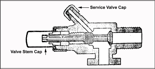
Refrigeration service valve diagram
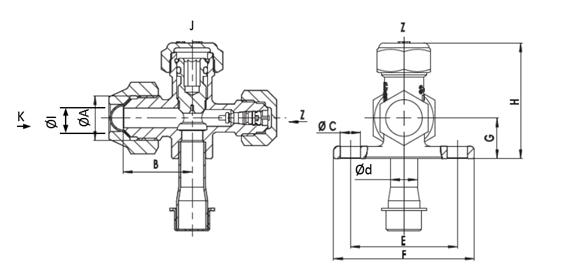
Service valve diagram Hi all, does antbody know where i can get a see through diagram of a normal refrigeration valve (the valve that you connect your gauges to, sometimes called a rotor lock valve). I've tried explaining it to my boy but it's better with someting he can see. Refrigeration cycle PV diagram. click on images to expand the view. C → D: low-pressure vapor refrigerant flows into the compressor suction and discharges into compressed high-pressure vapor. D → A: pressurized refrigerant vapor condenses in the liquid state at constant pressure, rejection of heat to the environment. The direction of refrigerant flow depends on valve placement (low side or high side) in a system. The service port is completely closed off. FRONT-SEATED. • Path between port 1 and port 2 is dosed, resulting in no refrigerant flow through the valve. • System components on the port 1 side of the valve are isolated from those on the port 2 side.
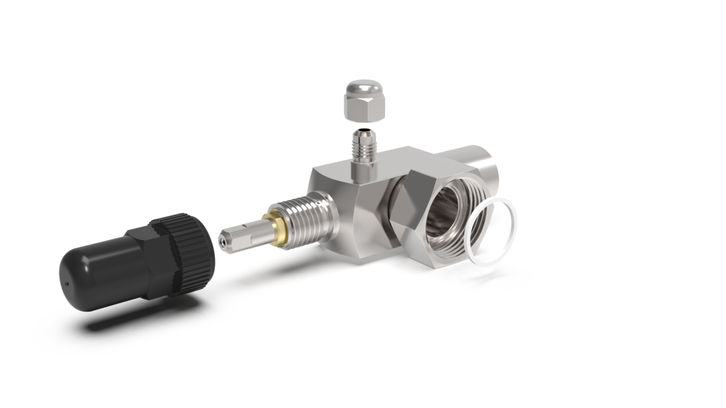
Refrigeration service valve diagram. Figure 26-1 shows some different service valves. Service valves are devices that allow access to the sealed refrigeration system. The most economical way this ... A description of the design of the service valve used on air conditioning units since the early 90s. Leak problems and brazing are covered.This video is par... Pneumatic Valves & Valve Systems. Air Preparation. Angle Seat, Pinch & Diaphragm Valves. Smart Solutions & Technologies . Miniature Solenoid Valves & Solutions. Vacuum Technologies. Combustion Products. Dust Collector Products. Sensors & Controls. Precision Regulators & Valves. Instrumentation Valves. Accessories. Brands ASCO. AVENTICS. TESCOM. TopWorx. Control & Safety Systems. … Service valves are found in many applications of an air conditioning and refrigeration system. Knowing the common valve positions is key to servicing and tr...
View and Download Samsung RF32FMQDBSR/AA service manual online. FRENCH DOOR REFRIGERATOR. RF32FMQDBSR/AA refrigerator pdf manual download. Also for: Rf34h9950sr/aa, Rf34h9950s4/aa, Rf24j9960s4/aa, Rf34h9960s4/aa. Mechanical refrigeration, is the utilization of mechanical components arranged in a "refrigeration system" for the purpose of transferring heat. E). Refrigerants , are chemical compounds that are alternately compressed and condensed into a liquid and then permitted to expand into a vapor or gas as they are pumped through the mechanical refrigeration system to cycle. 21.11.2001 · Requirement’s assessments, calculate refrigeration capacity, select equipment and components, make flow diagram, Compile material list, Price material list, establish all other expenses, arrive at final selling price, commencing with small thermosyphon plant, followed by simple pump re-circulation plant, thereafter more complex plants, Course can be extended to last longer or be … Outside AC Unit Diagram | Split Air Conditioner Outdoor Valves Hvac Air ... Refrigeration And Air Conditioning, Hvac Air Conditioning, Aircon Repair, ...
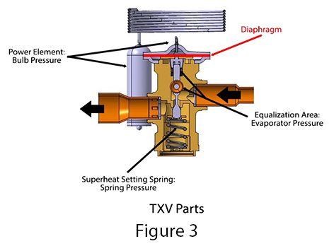
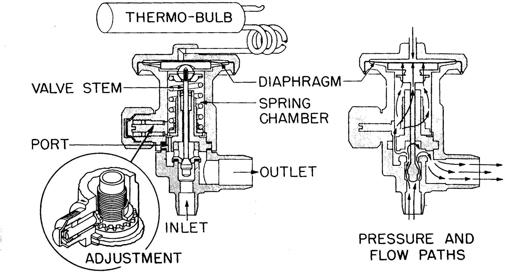
Manual Automation of Commercial Refrigeration Plant Expansion valves Upper diagram: The diagram shows an evaporator, which is fed by a thermostatic expansion valve with internal pressure equalization. The degree of opening of the valve is regulated by: Pressure p b in the bulb and capillary tube acting on the upper side of the diaphragm and 2 Mar 2018 — Back-Seated (all the way out, fully counter-clockwise) · Front-Seated (all the way in, fully clockwise) · Mid-Seated (valve in the center position ... (RSR) Operating Procedure Diagram. Special note for the RSR operation procedure diagram document: An RSR System is a self-contained package consisting of, among other things, a refrigerant compressor, storage receiver, water-cooled condenser and necessary valves and hoses, used to charge and remove refrigerant from a centrifugal chiller. P art Number 8014793 6/18 S Model Air Water Remote Ice Machines Technician’s Handbook
Refrigeration Sales inc now in its third generation as a family owned business It was founded in 1968 and has been a pioneer for forty years in both steel and brass service valves focused on the Refrigeration and air conditioning markets both OEM and aftermarkets .Refrigeration Sales inc also manufacturer a complete range of
High quality HVAC Tools for NZ Air Conditioning and Refrigeration service. Excellent customer service. Best Price Guarantee. Free Express Shipping. Skip to content. 09 216 9912 . info@hvactools.co.nz. Contact Us. Cart / $ 0.00. 0 Main Menu. PACKAGE DEALS; PROMOTIONS; PRODUCTS; FAQs; Search … Search. 10% OFF ALL SPIN FLARING AND SWAGING TOOLS SALE ENDS 30/11/2021. Best …
Diagram showing the components of a liquid-cooled chiller . The shell-and-tube heat exchanger which transfers heat from refrigerant to water which is circulated through cooling tower, and rejects heat. Key components of the chiller: Refrigeration compressors are essentially a pump for refrigerant gas. The capacity of the compressor, and hence the chiller cooling capacity, is measured in ...
Ball Valves FLOW CONTROLS FLOW CONTROLS 5 Ball valves are used in a wide variety of air conditioning and refrigeration applications. They can be used for both liquid and gas applications. Ball valves are commonly used for isolating purposes. All ball valves are suitable for HCFC and HFC refrigerants, along with their associated oils.
The direction of refrigerant flow depends on valve placement (low side or high side) in a system. The service port is completely closed off. FRONT-SEATED. • Path between port 1 and port 2 is dosed, resulting in no refrigerant flow through the valve. • System components on the port 1 side of the valve are isolated from those on the port 2 side.
Turn Of The Screw Adjusting Tecumseh Or York Compressor Service Valves On Your Car S Ac Classic Auto Air Air Conditioning Heating For 70 S Older Cars Trucks
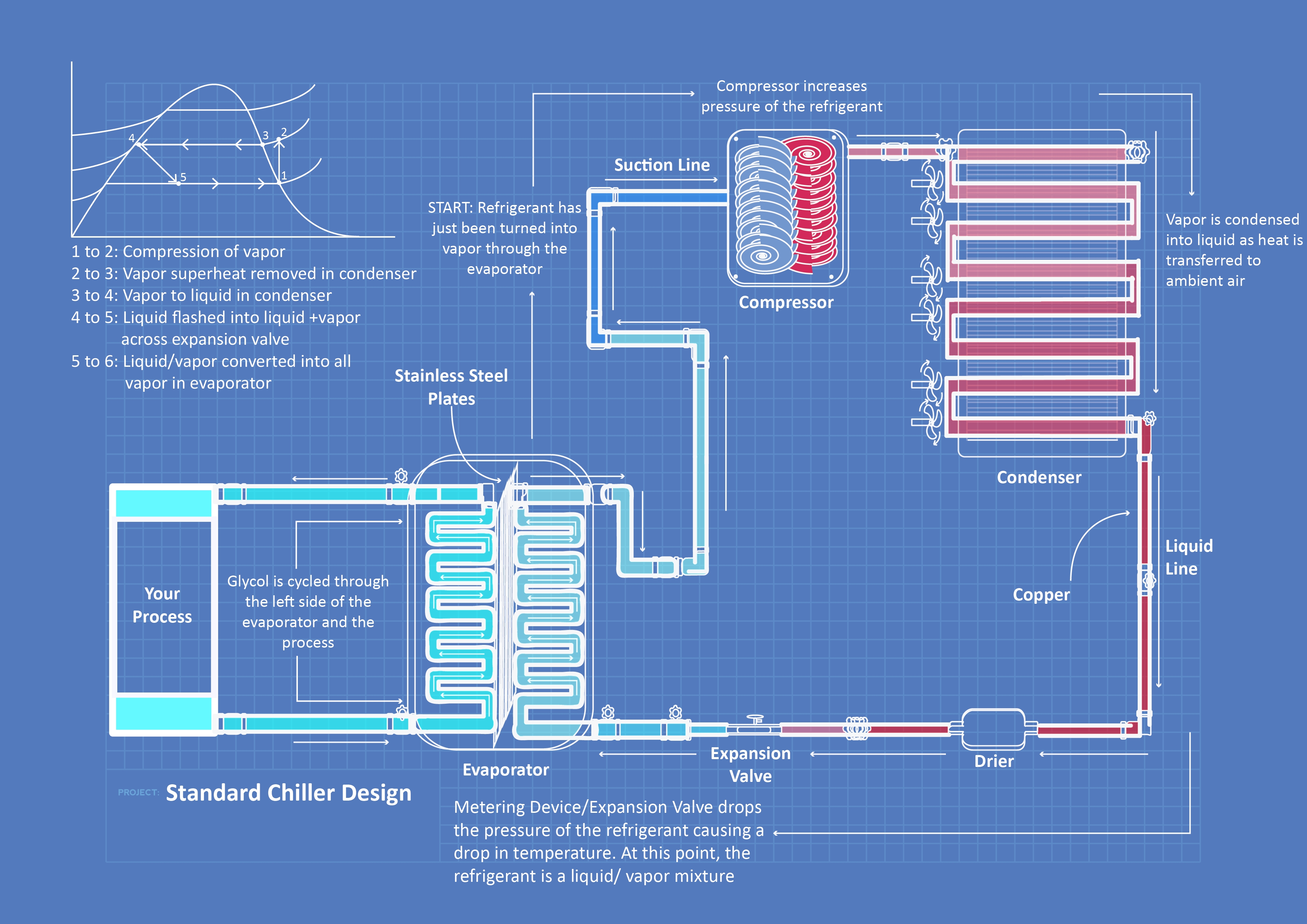
Refrigeration cycle PV diagram. click on images to expand the view. C → D: low-pressure vapor refrigerant flows into the compressor suction and discharges into compressed high-pressure vapor. D → A: pressurized refrigerant vapor condenses in the liquid state at constant pressure, rejection of heat to the environment.

Business Office Industrial Hvac Refrigeration Gauges Probes Suneducationgroup Com Hvac A C Refrigeration Test Charging Manifold Gauge Set
Service valve diagram Hi all, does antbody know where i can get a see through diagram of a normal refrigeration valve (the valve that you connect your gauges to, sometimes called a rotor lock valve). I've tried explaining it to my boy but it's better with someting he can see.

Refrigeration King Valve Diagram 1 Unbelievable Facts About Refrigeration King Valve Diagram Unbelievable Facts Diagram Facts

Turn Of The Screw Adjusting Tecumseh Or York Compressor Service Valves On Your Car S Ac Classic Auto Air Air Conditioning Heating For 70 S Older Cars Trucks











0 Response to "37 refrigeration service valve diagram"
Post a Comment