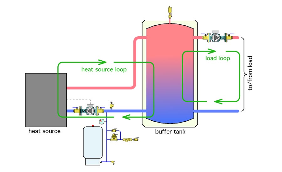
39 buffer tank piping diagram
Different temperatures needed in same piping system z180F for DHW z120F for radiant. 4 DECOUPLERS Closely Spaced Tees Buffer TankHydraulic Separator (depends) DECOUPLER Head = 0' PRIMARY FLOW TERMINAL UNIT Head = 10' - 20' CLOSELY SPACED TEES Distance Between Tees as Short as Possible (Tee to Tee). ® BUFFER TANK The HSS ® Buffer Tank can have several loops or circuits and each one should be purged separately. The HSS Buffer Tank shall be filled with water prior to running any of the circulator pumps. Keep a water source nearby to fill the tank as necessary. As air is relieved from the system piping water will need to be added.
12. Use either indirect/tank sensor or system/pipe sensor mounted on common return to the boiler. 13. Wire the tank or system/pipe sensor connected to the DHW sensor terminals on the follower boiler addressed as #1. 14. The system/pipe sensor must be placed on common piping to the tank, as close to the tank as possible. 15.
Buffer tank piping diagram
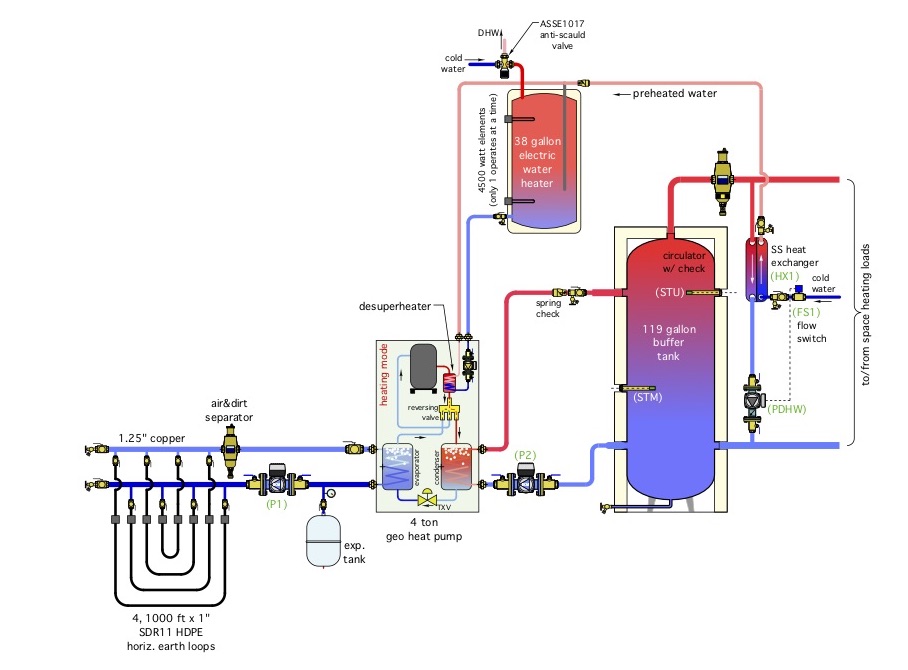
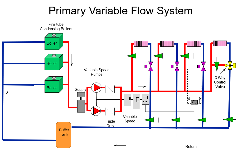
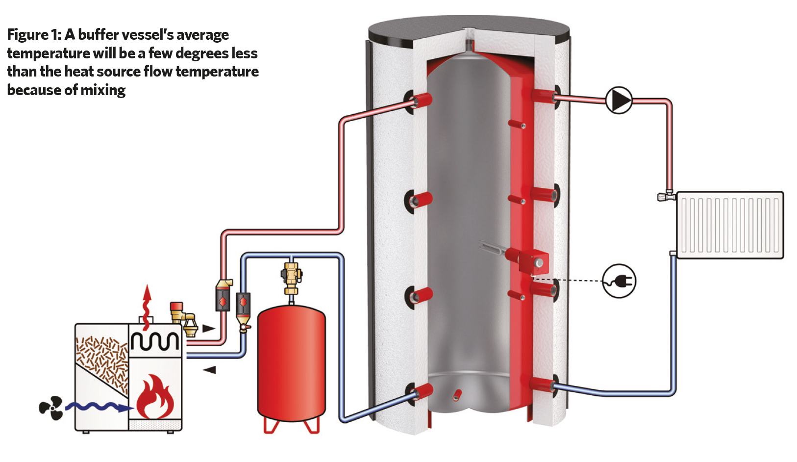
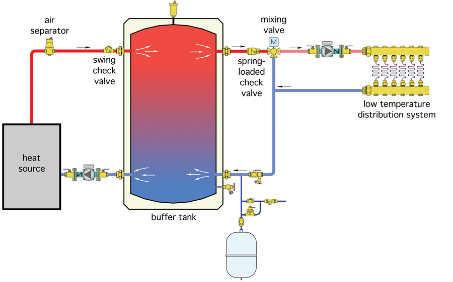
Downstream Tank: The piping shown in Figures 1,2 and 3 all involve four principal piping connections to the buffer tank, two into the upper portion, and two into the lower portion. Although these principal connections can function well, they are not the only way to connect a buffer tank into the system. After looking over many schematics from European sources, especially those associated with ... There was a diagram for a buffer tank published in the manual for the unit -- a Carrier badged Tranquility 27.) Attached is a sketch of the connections. Specifically I am curious that the hot water from the geo unit seems to mix with the cold water supply, and there is no kind of shutoff or valve there. An example of piping a buffer tank follows showing a water source heat pump application. In all applications note that the tank top fitting should be piped ...8 pages
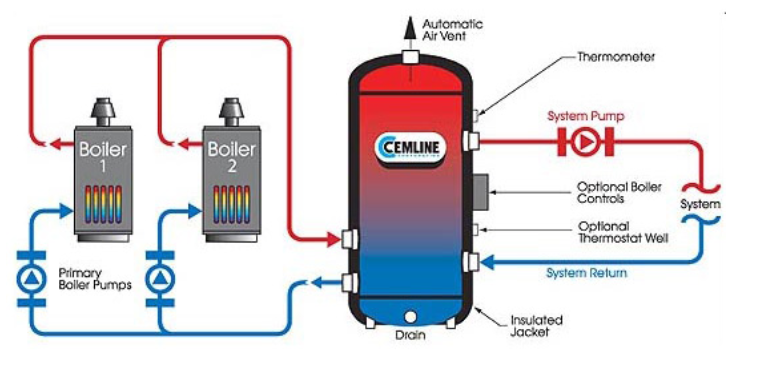
Buffer tank piping diagram. On the following page, an example of piping a buffer tank is provided, which shows a water source heat pump application. In all applications, note that the ...12 pages Either the traditional buffer tank piping shown in Figure 1 or the alternate method shown in Figure 5 can be used. Both have been used on many successful installations. It’s likely to come down to what tanks are available, how the piping connections on the tank are sized and located, and how those tanks would be optimally located in ... A: Buffer tanks provide extra water volume in a closed chilled water system. Q:Are buffer tanks used in every chilled water system? A: No. Some systems have an adequate volume of water in them so the extra storage provided by the buffer tank is not required. Q: How do they work? A: The added capacity, provided by the tank, reduces Product Drawings. Piping Diagram. Technical Papers. 3D-Drawings. Spec Sheets. CEMLINE® has made a series of typical piping arrangements for the Model Series: SEH, SSH, SWH, and USG. These drawings are in .DWG format or Adobe®Acrobat® (PDF) format. The Acrobat Reader is available free from Adobe. Note: Select the model and click on the ...
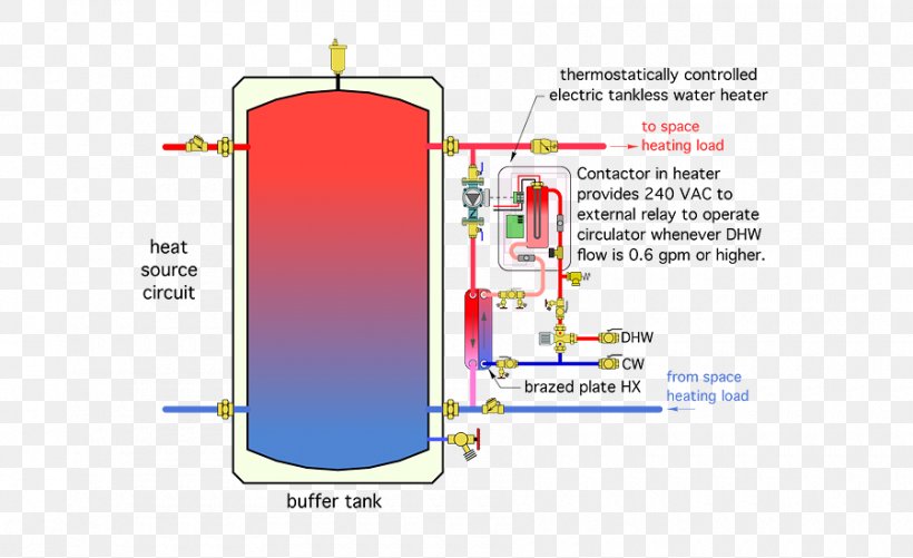
... including a wood gasifying boiler, stratification buffer tanks, solar DHW tank and a thermal solar system with flat plate collectors. Heating diagrams. Buffer tanks are available in 22, 40, 60, 80, and 115 gallon capacities. ... An example of piping a buffer tank follows showing a water source heat pump application. In all applications note that the tank top fitting should be piped the distribution supply line to the air purger and vent. This way the tank will be self Choose the HF-80-BT buffer tank. (100-90) x 500 BUFFER TANK SIZING: CALCULATING CAPACITY V = T x (Q heat input - Q min. heat load) Tank temperature rise X 500 V = Buffer Tank Volume (Gallons) T = Desired Heat Source “on cycle” (Min.) Q Heat Source = Heat Source Output to Minimum Load Q Min. Heat Load = Heat Output to Minimum Load Tank Temp. 22 Aug 2018 — Looking for a piping digram for the use of a buffer tank. We've installed many boilers with indirects, but never had to use a buffer tank ...
An example of piping a buffer tank follows showing a water source heat pump application. In all applications note that the tank top fitting should be piped ...8 pages There was a diagram for a buffer tank published in the manual for the unit -- a Carrier badged Tranquility 27.) Attached is a sketch of the connections. Specifically I am curious that the hot water from the geo unit seems to mix with the cold water supply, and there is no kind of shutoff or valve there. Downstream Tank: The piping shown in Figures 1,2 and 3 all involve four principal piping connections to the buffer tank, two into the upper portion, and two into the lower portion. Although these principal connections can function well, they are not the only way to connect a buffer tank into the system. After looking over many schematics from European sources, especially those associated with ...
Hydronic Heating Buffer Tanks Part 2 Sizing R L Deppmann
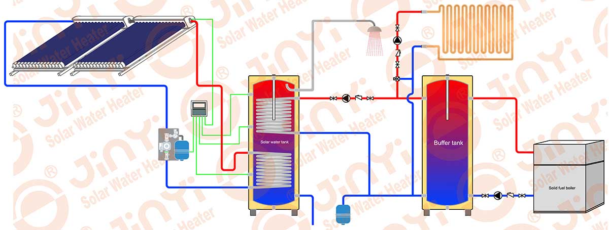
Buffer Tanks Buffer Storage Tanks Jinyi Hot Water Tanks

Impovements To Ergomax Buffer Tanks
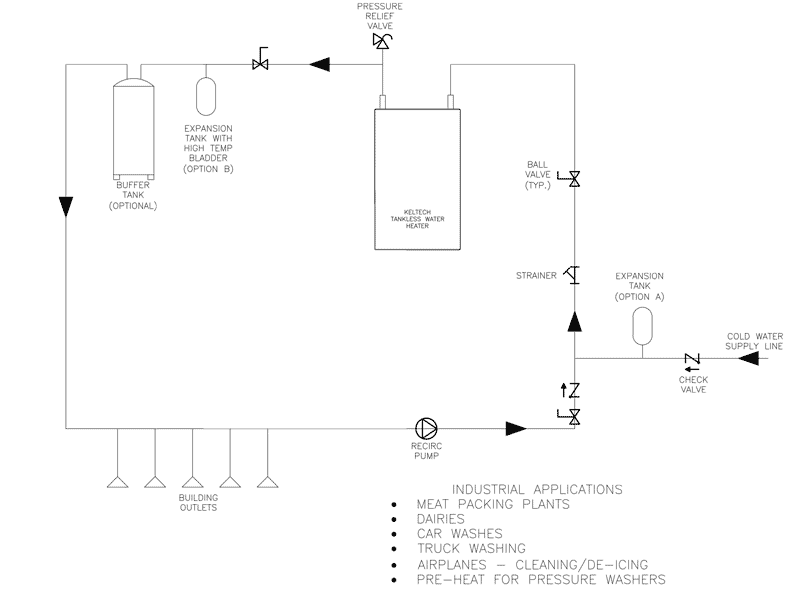
On Demand Heater With Buffer Tank Plumbing Diagram Bradley Corporation
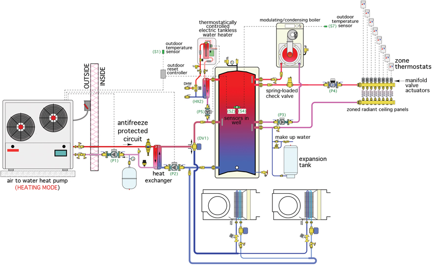
Heat Pump Plus Hpac Magazine
Combined Btus Hpac Magazine

Heating Diagrams For Boilers Buffer Tanks And Solar Collectors
Hydronic Heating Buffer Tanks Part 2 Sizing R L Deppmann
1

Heatspring Magazine 2 Pipe Versus 4 Pipe Buffer Tank Configurations
Hot Water Storage Tank Water Heating Water Tank Storage Water Heater Png 900x550px Hot Water Storage

Contamination In Ss 316l Pipe Jacket Cr4 Discussion Thread
Do You Need A Chilled Water Buffer Tank Tec News

The Mice Absorber Hydrogen System This System Includes The Hydride Download Scientific Diagram

Alternate Methods To Pipe A Buffer Tank 2014 10 22 Plumbing And Mechanical Plumbing Mechanical
Hydronic Heating Buffer Tanks Part 3 Variable Primary

Math For Short Cycling Blues Heating Help The Wall
Optimising Thermal Store Design For Chp Cibse Journal
2
2

10 Piping Schematic Of The Buffer Tanks Crofoot 2012 Download Scientific Diagram

Oil Buffer Tank Left Nitrogen Expansion Tank For Water Centre Download Scientific Diagram
One Side Or The Other Hpac Magazine
Is This Desuperheater Buffer Tank Plumbed Correctly Geoexchange Forum
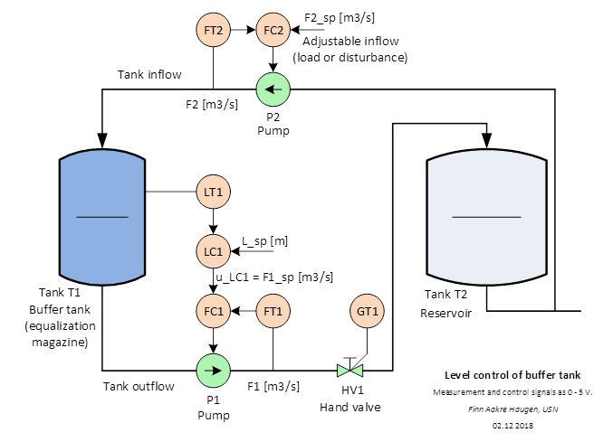
University College Of Southeast Norway

Buffer Tank Piping Diagram Heating Help The Wall
10 Piping Schematic Of The Buffer Tanks Crofoot 2012 Download Scientific Diagram
Chilled Water

Proper Buffer Tank Sizing For Optimum System Performance Contractor
Washington Thermal Expansion Tank With Geothermal Dsh Geoexchange Forum
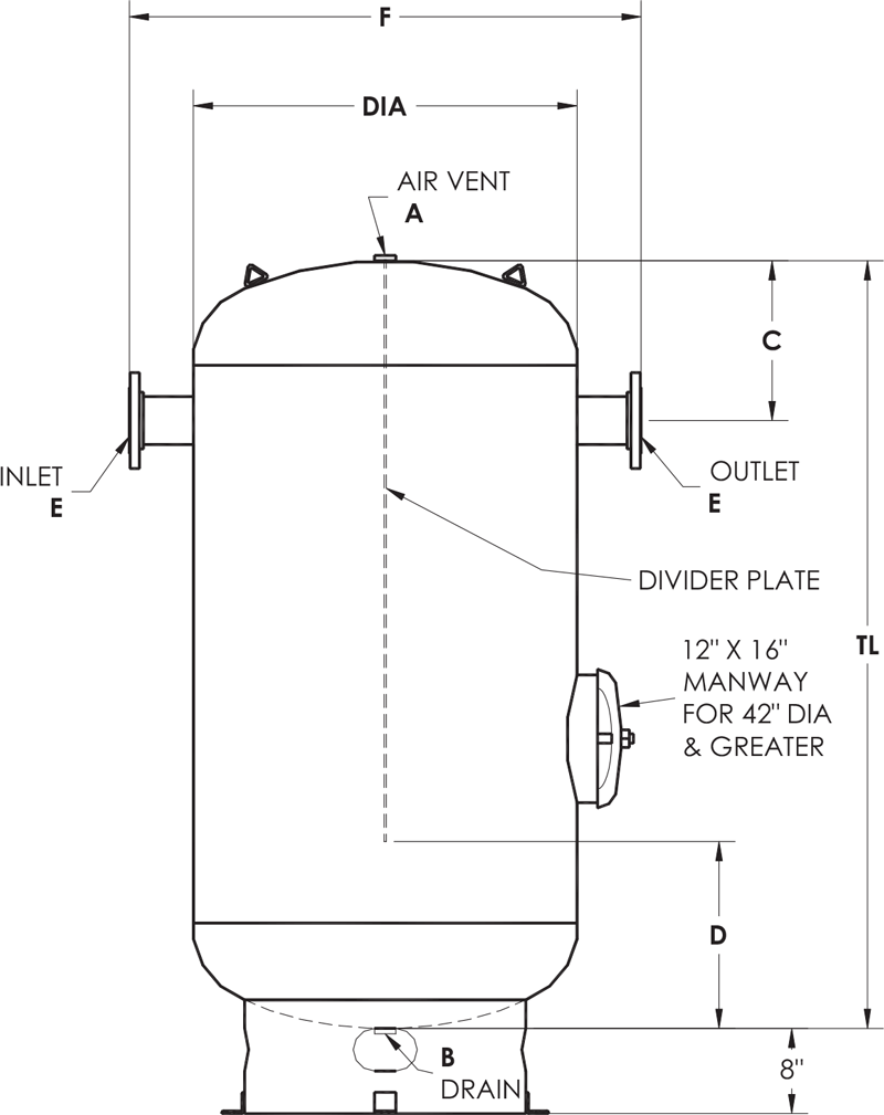
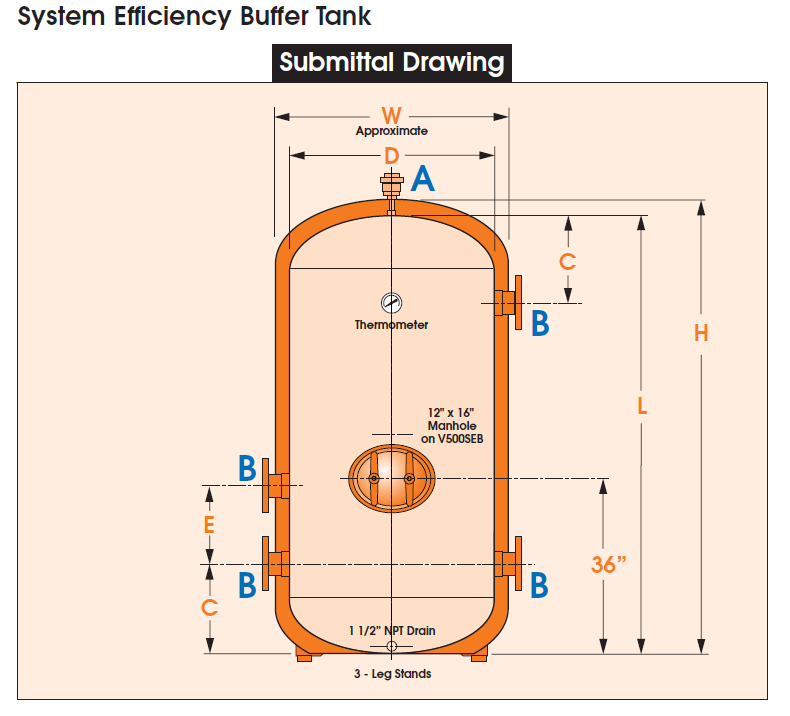
Asme Chilled Water Buffer Tanks Dimension Diagram Elbi Of America
John Siegenthaler Due Diligence 2020 09 22 Plumbing Mechanical
2

Buffer Tank Piping Heating Help The Wall

Buff Up Your Knowledge Of Buffer Tanks Kensa Heat Pumps

Buffer Tanks Joule
.jpg)
Chilled Water Hvac

Heatspring Magazine 2 Pipe Versus 4 Pipe Buffer Tank Configurations

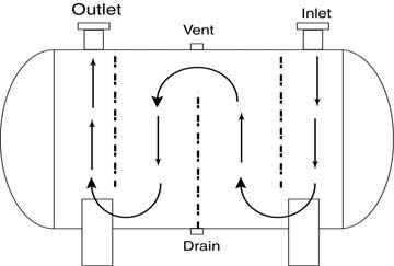
Typical P Id Arrangement For Storage Tanks Enggcyclopedia
0 Response to "39 buffer tank piping diagram"
Post a Comment