37 4 bit carry look ahead adder circuit diagram
A carry-look-ahead adder decreases the propagation delay by including more complex hardware. In this configuration, the ripple carry design is suitably transformed such that the carry logic over fixed groups of bits of the adder is reduced to two-level logic. Below is the circuit diagram for 4-bit look ahead carry adder. 4-bit-Carry-Look-ahead-Adder-Circuit-Diagram. 8-bit and 16-bit Carry Look-ahead Adder circuits can be designed by cascading the 4-bit adder circuit with carry logic. Advantages of Carry Look-ahead Adder. In this adder, the propagation delay is reduced. The carry output at any stage is dependent only on the initial carry bit of the beginning stage.
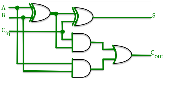
The block diagram of a 4-bit Carry Lookahead Adder is shown here below - The number of gate levels for the carry propagation can be found from the circuit of full adder. The signal from input carry C in to output carry C out requires an AND gate and an OR gate, which constitutes two gate levels.

4 bit carry look ahead adder circuit diagram
Nov 11, 2017 · 4 Bit Adder Gate Level Design Retrieved From 1 Scientific Diagram. Carry Look Ahead Adder 4 Bit Gate Vidyalay. Solved Implement The 4 Bit Binary Adder Subtractor Logic Chegg Com. Combinational and sequential design of a 4 bit adder ha circuit scientific diagram coa binary subtractor javatpoint discussion with example full using logic gates in ... May 31, 2021 · The carry output Boolean function of each stage in a 4 stage carry look-ahead adder can be expressed as . From the above Boolean equations we can observe that does not have to wait for and to propagate but actually is propagated at the same time as and . Since the Boolean expression for each carry output is the sum of products so these can be implemented with one level of AND gates followed by an OR gate. Answer: * To understand what’s the importance of Carry Look Ahead Adder ( CLA ) (also called Parallel Adder) in ALU’s , first, you need to realize what led to development of such an adder. Though there are half-adders/ 4-bit ripple adders (also called Serial Adder) available in market, they are ...
4 bit carry look ahead adder circuit diagram. Fig 2 – Ripple carry adder Stages. In 4 bit adder, the time delay for a valid output is the sum of time delay of 4 full adders, if there is an ‘n’ bit adder, than the time delay will be the sum of time delay of ‘n’ full adders. It means, higher the bit size of the numbers, the late the answer we will get.So it is not an efficient design for complex and fast working systems. To construct 8 bit, 16 bit, and 32-bit parallel adders, we can cascade multiple 4-bit Carry Look Ahead Adders with the carry logic. A 16 bit CLA adder can be constructed by cascading four 4 bit adders with two extra gate delays, while a 32 bit CLA adder is formed when two 16 bit adders are cascaded to form one system. 4-Bit Carry Look Ahead Adder-. Consider two 4-bit binary numbers A 3 A 2 A 1 A 0 and B 3 B 2 B 1 B 0 are to be added. Mathematically, the two numbers will be added as-. From here, we have-. C 1 = C 0 (A 0 ⊕ B 0) + A 0 B 0. C 2 = C 1 (A 1 ⊕ B 1) + A 1 B 1. C 3 = C 2 (A 2 ⊕ B 2) + A 2 B 2. Also Read-Full Adder Working . 4-Bit Carry Look Ahead Adder- Consider two 4-bit binary numbers A 3 A 2 A 1 A 0 and B 3 B 2 B 1 B 0 are to be added. Mathematically, the two numbers will be added as- From here, we have-C 1 = C 0 (A 0 ⊕ B 0) + A 0 B 0. C 2 = C 1 (A 1 ⊕ B 1) + A 1 B 1. C 3 = C 2 (A 2 ⊕ B 2) + A 2 B 2. C 4 = C 3 (A 3 ⊕ B 3) + A 3 B 3 . For simplicity, Let-
What is the purpose of using carry-look-ahead generator? Derive the Boolean equations and draw a 4 bit carry-look-ahead generator circuit. Question: 2. [3+2+2+3 = 10 points] Draw the logic diagram of a full adder circuit. Also show the carry propagator (Pi) and carry generator (Gi). What is the purpose of using carry-look-ahead generator? Answer: * To understand what’s the importance of Carry Look Ahead Adder ( CLA ) (also called Parallel Adder) in ALU’s , first, you need to realize what led to development of such an adder. Though there are half-adders/ 4-bit ripple adders (also called Serial Adder) available in market, they are ... May 31, 2021 · The carry output Boolean function of each stage in a 4 stage carry look-ahead adder can be expressed as . From the above Boolean equations we can observe that does not have to wait for and to propagate but actually is propagated at the same time as and . Since the Boolean expression for each carry output is the sum of products so these can be implemented with one level of AND gates followed by an OR gate. Nov 11, 2017 · 4 Bit Adder Gate Level Design Retrieved From 1 Scientific Diagram. Carry Look Ahead Adder 4 Bit Gate Vidyalay. Solved Implement The 4 Bit Binary Adder Subtractor Logic Chegg Com. Combinational and sequential design of a 4 bit adder ha circuit scientific diagram coa binary subtractor javatpoint discussion with example full using logic gates in ...


0 Response to "37 4 bit carry look ahead adder circuit diagram"
Post a Comment