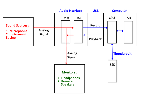
42 audio signal flow diagram
Block Diagram Signal Flow Graph To convert from a block diagram to a signal flow graph: 1. Identify and label all signals on the block diagram 2. Place a node for each signal 3. Connect nodes with branches in place of the blocks Maintain correct direction Cubase Signal Routing. Input channels: This diagram demonstrates the flow from the physical inputs through an input channel, before the signal reaches an audio channel. FX channels have the same basic signal flow. While Cubase 's graphical environment makes the application easy to use, it's not always clear exactly where signals are being routed.
Signal flow is the flow of the audio signal from the sources of input to the places of output, from sound-to-speaker, if you will. Learning how to set up the stage, you saw how the signal flows from an electric guitar to a pedal board to a DI box and then into a stage jack.
Audio signal flow diagram
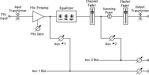
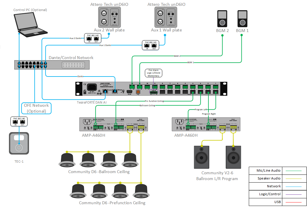
Basic Flow Chart Symbols AUDIO SIGNAL PATH - a wire AMPLIFIER - signal flows in the direction the triangle is pointing. RESISTOR. Sometimes shown as a simple rectangle - VARIABLE RESISTOR, rheostat - a passive level control (can only reduce signal going through). A fader or rotary pot ACTIVE AMPLIFIER - can increase signal passing through as ... A signal flow diagram shows the signal path (audio, video, network, control, etc.) from inputs to outputs, for the entire AV system. It's essentially a blueprint for the system… and would you buy a house where they didn't have a blueprint? Understanding the flow of signals within your home theatre starts with becoming familiar with the three distinct types of devices that your home entertainment components fall into: Source Devices, Hub Devices & Sink Devices. Source Devices are easy to identify as they generally only have AV Outputs - they play your media and send the audio and ...
Audio signal flow diagram. The final element in the superheterodyne receiver block diagram is shown as an audio amplifier, although this could be any form of circuit block that is used to process or amplified the demodulated signal. Block diagram summary. The diagram above shows a very basic version of the superhet or superheterodyne receiver. Working of Common Emitter Amplifier. The below circuit diagram shows the working of the common emitter amplifier circuit and it consists of voltage divider biasing, used to supply the base bias voltage as per the necessity. The voltage divider biasing has a potential divider with two resistors are connected in a way that the midpoint is used for supplying base bias voltage. To make things easier for you, we're tackling the basics of mixing console signal flow. The Function Of A Mixing Console. A mixing console allows you to feed your recorded signal into your DAW and then monitor the sound as a full mix via the console faders. Nothing is actually recorded onto the console. Class C power amplifier circuit diagram, theory, output characteristics, DC load line, efficiency, ... conduct for less than one half cycle of the input signal. ... (transistor) here is to produce a series of current pulses according to the input and make it flow through the resonant circuit.
Signal Flow Chart Audio routing is built on a set of stages that follow a sound all the way from its source, input and conversion, channel strip, output stage and ultimately through the speaker and into your ears. Signal Flow - How it works I hope you had a good look at the previous diagram. Get your free Backstage Toolkit at https://proaudioexp.com/pages/backstage-toolkit. Audio Engineer David Wills' (Michael Jackson, Whitney Houston) personal t... Hard drive > insert #1 (compressor plug-in) > insert #2 (EQ plug-in) > fader. Everything else about the basic signal flow remains the same. Two crucially important facts to note about this order: 1. The plug-in processing on the vocal track is not recorded to the vocal audio file, it is only being monitored. 2. From simple to complex, the ConnectCAD add-on to Spotlight and Design Suite gives AV system designers the power to lay out signal flows in an easy-to-read format.
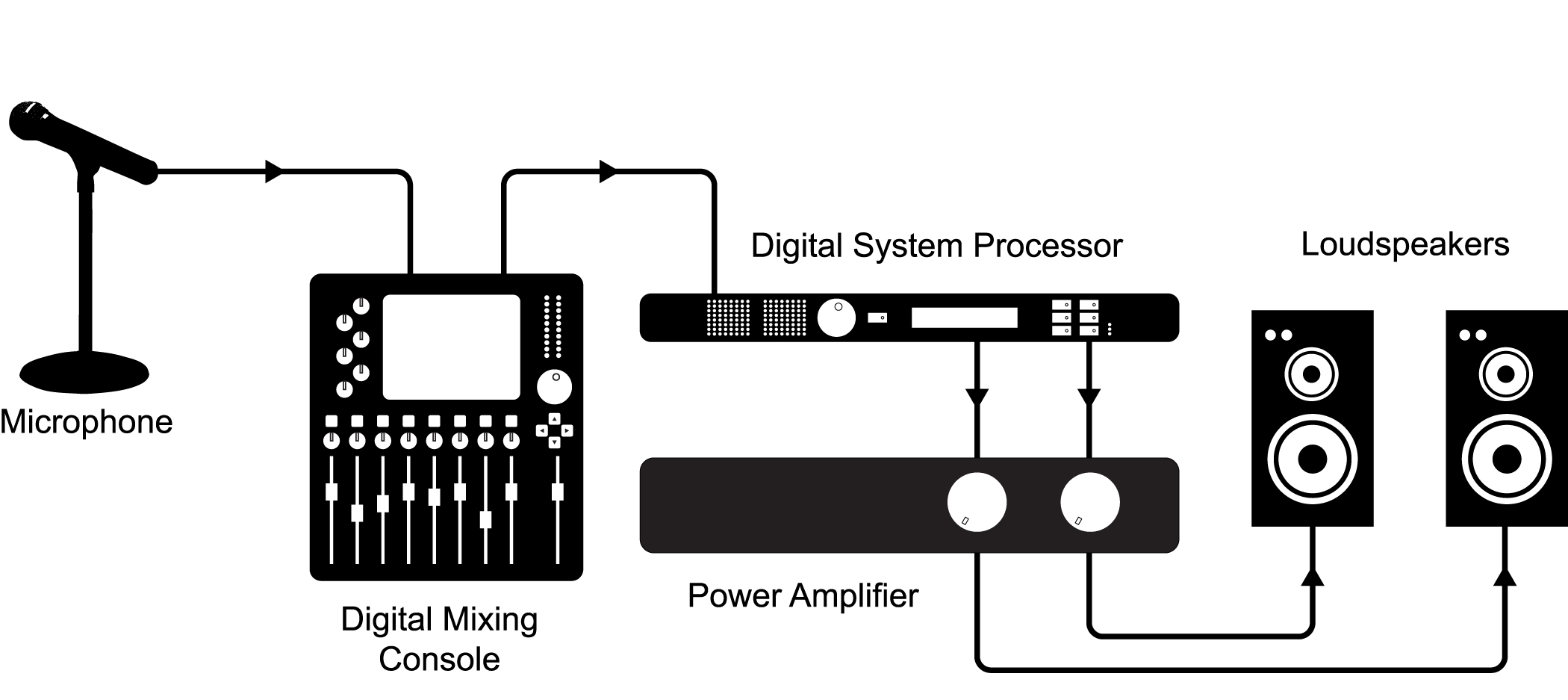
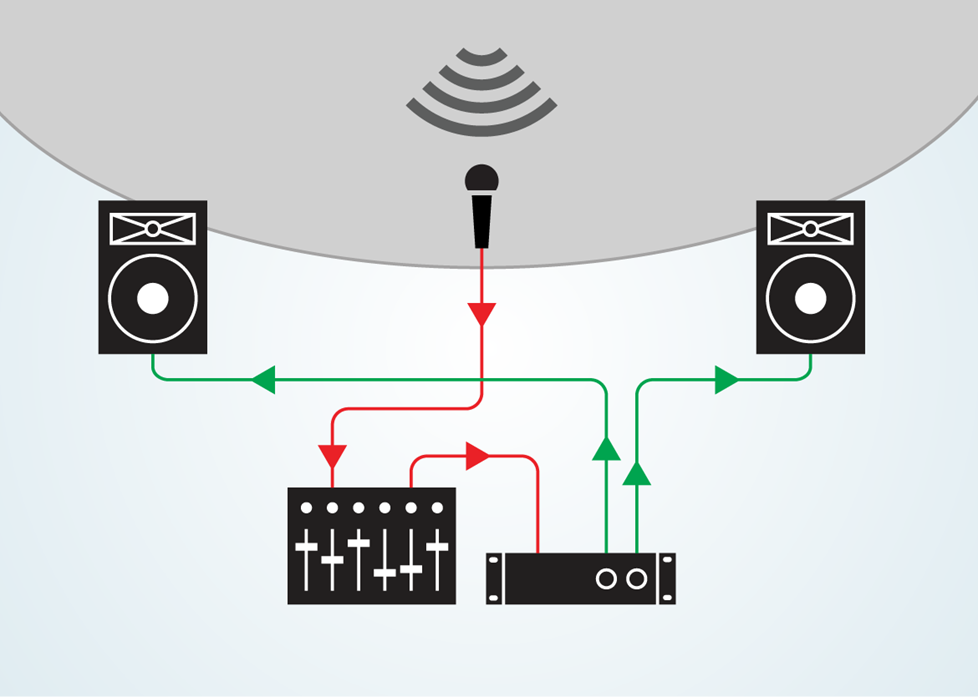
In this guide, let’s learn in detail about Push Pull Amplifiers. We’ve covered theory and applications behind a push pull amplifier. We’ve also demonstrated different types of push pull amplifiers, like Class A, Class B and Class AB push pull amplifier models. For helpful Church Technology resources check outEllisProMedia.comwww.facebook.com/EllisProMediawww.instagram.com/ellispromediaIn this video we are going to ... Signal flow begins at the sound source, with a transduction stage. Transduction is the process of converting one type of energy into another form of energy. Within our diagram, the microphone(s) take the sound waves from the sound source and convert the sound waves into an electric current (through the process of transduction). Signal flow diagram illustrating the path that a signal follows in a typical PA system. An input device is the interface between a sound source and the sound system. In most cases, it will consist of either a microphone or a direct input (DI) box.
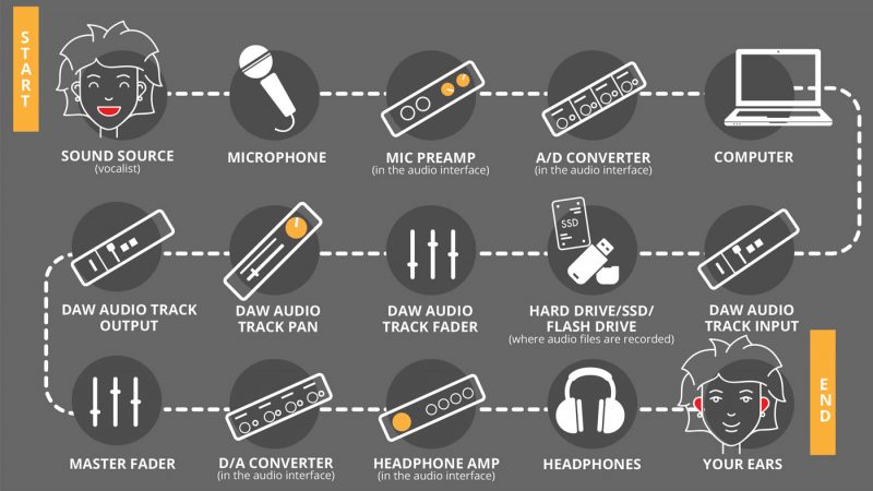
HARD DRIVE /SSD /FLASH DRIVE DAW AUDIO TRACK FADER DAW AUDIO TRACK PAN (where audio les are recorded) DAW AUDIO TRACK INPUT COMPUTER A/D CONVERTER (in the audio interface) MIC PREAMP (in the audio interface) SOUND SOURCE MICROPHONE (vocalist) SIGNAL FLOW CHART. Title: signal-flow-chart-printer-friendly-recording
Delay is an audio signal processing technique that records an input signal to a storage medium and then plays it back after a period of time. When the processed audio is blended with the unprocessed audio, it creates an echo-like effect, whereby the original audio is heard followed by the delayed audio.The delayed signal may be played back multiple times, or fed back into the …
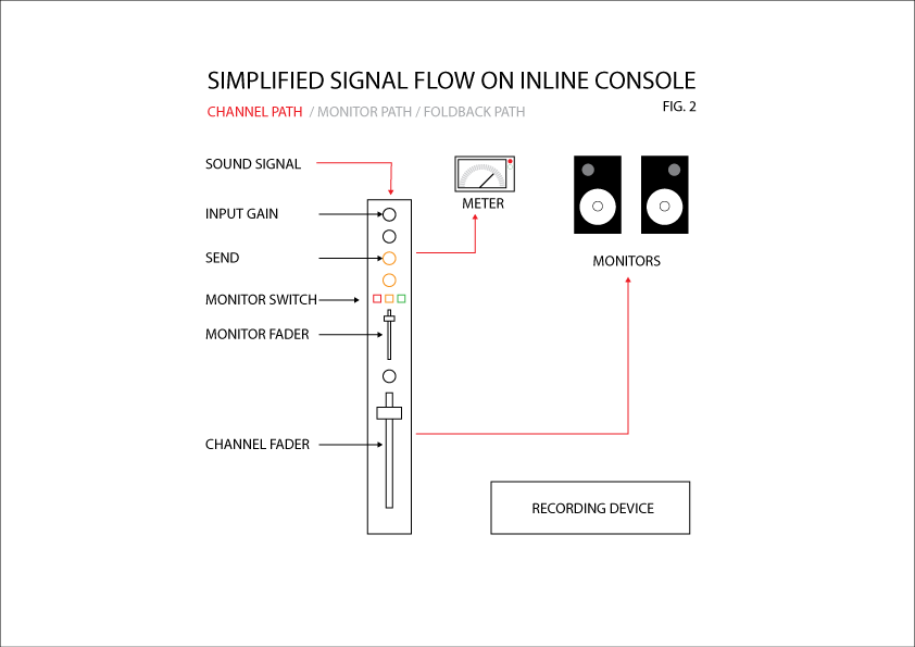
A (very) simple diagram of the channel path signal flow through an inline console. The signal coming directly from the studio/musician will go into and through a channel on the console. This signal path is called Channel Path. We can meter it and we can monitor it. Typically the fader on Channel Path is at unity gain and the signal is set to ...
Audio signal flow is the path an audio signal takes from source to output. The concept of audio signal flow is closely related to the concept of audio gain staging; each component in the signal flow can be thought of as a gain stage . In typical home stereo systems, the signal flow is usually short and simple, with only a few components.
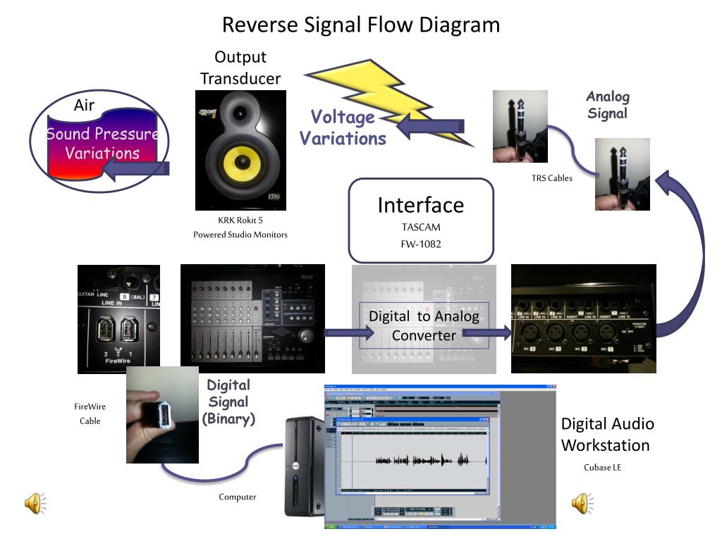
Result: Audio is in our DAW: At this stage, our signal has flowed from its origin as a physical sound to a pre-amp and then to an A/D converter which sends the resulting digital audio to our PC. Out. The next step of the signal flow is similar to the first but in reverse.
av signal flow diagram output to vtc codec output to vtc codec from matrix switcher from matrix switcher stereo dual wall-mounted video input speakers audio output audio output controller tcp/ip lan ctrl tcp/ip lanctrl tcp/ip lanctrl 65" flat panel display video input tcp/ip lanctrl tcp/ip lan scene (source) select audio volume / mute mic on ...
In this diagram you can see that you have a choice of two inputs, like on most standard mixers. MIC input as standard receives a 5mV signal from a microphone. The LINE input generally receives around 1 Volt. In order to deal with this, the mixer will have microphone PREAMPS in order to boost the MIC voltage to match the LINE level.
Understanding Signal Flow. Knowing the audio path through a mixing console is absolutely critical to a sound engineer's success. Using this information, the engineer can quickly TROUBLESHOOT the likely causes of common problems, and can even narrow down the possibilities of unexpected major problems. It can also prevent mistakes because you ...
A wiring diagram is a comprehensive diagram of each electrical circuit system showing all the connectors, wiring, terminal boards, signal connections (buses) between the devices and electrical or electronic components of the circuit. It also identifies the wires by wire numbers or colour coding.
digital signal. The STM32 MCUs and MPUs acquire digital data from the microphone(s) through particular pe ripherals to be pr ocessed and transformed into data standard for aud io. The audio data is then handled by the microcontroller according to the targeted audio application. Figure 1. Example of sound acquisition in audio application. a.
A step by step walk through the diagram. 1. Microphone->Mic Preamp. The microphone picks up the sound, and a mic level signal is sent to the microphone preamp. Since mic level signals are inherently weak, the preamp is needed to amplify it to a higher level. The amplified signal is known as line level. 2.
KVR Audio Forum - Program to draw signal flow diagrams (free) ? - DSP and Plug-in Development Forum
It's equal parts signal flow, miking technique, ear training, problem-solving, psychology and customer service. Let's take it from the top. Signal Flow. The most important skill you can have as a live sound engineer is a solid understanding of signal flow. Without it, there's no music, and you're not much of an engineer at all, actually.
Class D Audio Amplifier Design • Class D Amplifier Introduction • Gate Driver • MOSFET • Package • Design Example Theory of Class D operation, topology comparison How to drive the gate, key parameters in gate drive stage How to choose, tradeoff relationships, loss calculation Importance of layout and package, new packaging technology
Signal Demodulation. They are also used in the process of signal modulation because diodes can remove the negative element of an AC signal efficiently. The diode rectifies the carrier wave, turning it into DC. The audio signal is retrieved from the carrier wave, a process called audio-frequency modulation.
Radio Receiver Working Principle . In Figure 1, there are three radio stations each broadcasting at a different wavelength.Each station is broadcasting a radio signal consisting of a carrier wave and an audio signal. Station 1 is broadcasting at AM 920, …
Step 6 − Signal flow graph of overall system is shown in the following figure. Conversion of Block Diagrams into Signal Flow Graphs. Follow these steps for converting a block diagram into its equivalent signal flow graph. Represent all the signals, variables, summing points and take-off points of block diagram as nodes in signal flow graph.
It's actually kind of fun. 1. r/CommercialAV. For those of us that are interested in commercial audio, video, and control technologies in all sectors. This means government, corporate, or education, or other. Whether it's the latest and greatest Crestron touchpanel or a new Grommes Precision Amplifier, we want to know about it.
Conclusion: Signal Flow. Signal flow isn't just some technical concept audio engineers rant about to sound smart. It's a crucial part of figuring out how to solve problems while recording and mixing! I recommend saving both signal flow diagrams above so you can check them out in any session.
15.1.2020 · The contacts (denoted by 1 and 2) are good conductive materials that allow current to flow when they are in contact with each other. The coil and core work like an electromagnet. When tension is applied to the coil ends, it creates a magnetic field and pulls the pallet towards itself (the pallet in the yellow ring is released and the pallet in the green ring is pulled toward …
XTEN-AV Designer generates automated block schematics, rack layouts, ceiling speakers layouts, signal flow diagrams, cable schedules and scope of work documents. Edit auto-generated drawings and convert to other formats such as AutoCad and Visio.
Understanding the flow of signals within your home theatre starts with becoming familiar with the three distinct types of devices that your home entertainment components fall into: Source Devices, Hub Devices & Sink Devices. Source Devices are easy to identify as they generally only have AV Outputs - they play your media and send the audio and ...
A signal flow diagram shows the signal path (audio, video, network, control, etc.) from inputs to outputs, for the entire AV system. It's essentially a blueprint for the system… and would you buy a house where they didn't have a blueprint?
Basic Flow Chart Symbols AUDIO SIGNAL PATH - a wire AMPLIFIER - signal flows in the direction the triangle is pointing. RESISTOR. Sometimes shown as a simple rectangle - VARIABLE RESISTOR, rheostat - a passive level control (can only reduce signal going through). A fader or rotary pot ACTIVE AMPLIFIER - can increase signal passing through as ...









0 Response to "42 audio signal flow diagram"
Post a Comment