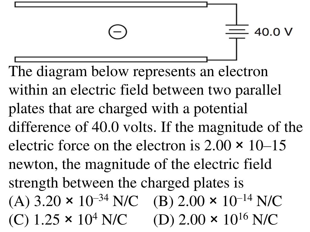
38 the diagram below represents an electron within an electric field
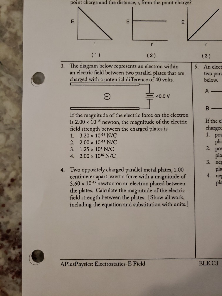
PDF 1.The electroscope shown in the diagram below is made ... 10.Two points, A and B, are located within the electric field produced by a -3.0 nanocoulomb charge. Point A is 0.10 meter to the left of the charge and point B is 0.20 meter to the right of the charge, as shown in the diagram below. Compared to the magnitude of the electric field strength at point A, the magnitude of the electric field PDF Nae Period Electrostatics-E Field - APlusPhysics 3. The diagram below represents an electron within an electric field between two parallel plates that are charged with a potential difference of 40 volts. If the magnitude of the electric force on the electron is 2.00 × 10⁻¹⁵ newton, the magnitude of the electric field strength between the charged plates is 1. 3.20 × 10⁻³⁴ N/C 2. 2.00 × 10 ...
PDF ELECTRIC FIELD WORKSHEET NAME: - Weebly 10.The diagram below represents an electron within an electric field between two parallel plates that are charged with a potential difference of 40.0 volts. A)3.20 10-34 N/C B)2.00 10-14 N/C C)1.25 104 N/C D)2.00 1016 N/C If the magnitude of the electric force on the electron is 2.00 ×10⁻¹⁵ newton, the magnitude of the electric field

The diagram below represents an electron within an electric field
en.wikipedia.org › wiki › MemristorMemristor - Wikipedia A memristor (/ ˈ m ɛ m r ɪ s t ər /; a portmanteau of memory resistor) is a non-linear two-terminal electrical component relating electric charge and magnetic flux linkage.It was described and named in 1971 by Leon Chua, completing a theoretical quartet of fundamental electrical components which comprises also the resistor, capacitor and inductor. Zeeman Effect - an overview | ScienceDirect Topics Generic energy diagram for Zeeman splitting of angular momentum vectors in applied magnetic field. Normal Zeeman effect. The normal Zeeman effect is observed in systems with closed shells of electrons and arises due to lifting of the orbital degeneracy by an external magnetic field of moderate strength. It is manifest as equally spaced fine structure lines, for example, in … Chemistry Final Exam Review - Part 3 - 2014-2015 - Quizlet Which electron dot diagram represents a molecule that has a polar covalent bond? B. ... The diagram below represents radiation passing through an electric field. The arrow labeled A most likely represents: D. Given the reaction. ... The diagram below represents a fission nuclear reactor. The arrows indicate the direction of flow of water.
The diagram below represents an electron within an electric field. SOLVED:The diagram below represents an electron within an ... The diagram below represents an electron within an electric field between two parallel plates that are charged with a potential difference of $40.0$ volts. If the magnitude of the electric force on the electron is $2.00 \times 10^{-}$ ${ }^{15}$ newton, the magnitude of the electric field strength between the charged plates is(A) $3.20 \times ... Electrostatics-E Field - Name: Period: Electrostatics-E ... The diagram below represents an electron within an electric field between two parallel plates that are charged with a potential difference of 40 volts. PDF Physics Week 2(Sem. 2) - St. Francis Preparatory School 17. Which diagram best illustrates the electric field around two unlike charges? 18. An electron is located in the electric field between two parallel metal plates as shown in the diagram below. A) positively, and the electric field is directed from plate A toward plate B B) positively, and the electric field is directed from plate B toward plate A PDF John Bowne High School Electric Field Strength 4. The diagram below represents a 1. Which graph best represents the relationship between the magnitude of the electric field strength, E, around a point charge and the distance, r, from 5. within an electric field between two parallel plates that are charged with a potential difference of 40.0 volts. '0.0 v
Physics Final Flashcards - Quizlet The diagram below represents a box sliding ... Which diagram correctly represents an electric field? 1. The height of an individual step on a staircase is closest to. ... magnitude 1.5 × 10⁻¹⁴ newton on an electron within the field. What is the magnitude of the electric field strength at the location of the aip.scitation.org › doi › 10Theoretical and practical aspects of the design and ... Jan 18, 2022 · Schematic diagram showing the phase-shifting effect on an incident plane electron wave of (left) a phase ramp and (right) a spiral phase mask. Readapted from “New approaches for phase manipulation and characterization in the transmission electron microscope,” with the permission of Federico Venturi. 32 32. PDF 1. The diagram below represents magnetic lines of 4. In ... 1. The diagram below represents magnetic lines of force within a region of space. The magnetic field is strongest at point (1) A (3) C (2) B (4) D 2. The diagram below shows the magnetic field that results when a piece of iron is placed between unlike magnetic poles. At which point is the magnetic field strength greatest? (1) A (3) C (2) B (4) D 3. educationstandards.nsw.edu.au › wps › wcmNSW Education Standards Authority A. Electron B. Gluon C. Muon D. Proton 4 An astronaut is travelling towards Earth in a spaceship at 0.8 c. At regular intervals, a radio pulse is sent from the spaceship to an observer on Earth. Which quantity would the astronaut and the observer measure to be the same? A. Length of the spaceship B. Speed of the radio pulses C. Momentum of the ...
(PDF) Electric Machinery Fundamentals - 5th Ed Chapman ... Electric Machinery Fundamentals - 5th Ed Chapman. Ziafat Shehzad. Download Download PDF. Full PDF Package Download Full PDF Package. This Paper. A short summary of this paper. 17 Full PDFs related to this paper. Read Paper. Download Download PDF. … CH150: Chapter 3 – Ions and Ionic Compounds – Chemistry A structural diagram of what this molecule would look like is shown below. Note that each straight line is being used here to indicate a covalent bond within the phosphate ion. Each straight line represents two electrons (or an electron pair) that is being shared between the atoms. Covalent bonding will be described in more detail in chapter 4. For now, it is important … EOF PDF A) B) C) D) - Forestville 8) The diagram below represents an electron within an electric field between two parallel plates that are charged with a potent ial difference of 40.0 volts. If the magnitude of the electric force on the electron is 2.00 x 10⁻¹⁵ newton, what is the magnitude of the electric field strength
Electron Flow - an overview | ScienceDirect Topics
PDF Physical Setting Physics 19 The diagram below represents an electron within an electric field between two parallel plates that are charged with a potential difference of 40.0 volts. If the magnitude of the electric force on the electron is 2.00 × 10⁻¹⁵ newton, the magnitude of the electric field strength between the charged plates is (1) 3.20 × 10⁻³⁴ N/C (3) 1.25 ...
Electric Field Lines: Multiple Charges | Physics
Solved point charge and the distance, r, from the ... - Chegg The diagram below represents an electron within an electric field between two parallel plates that are charged with a potential difference of 40 volts. 5. An elect two par: below. A - = 40.0 v В — If the magnitude of the electric force on the electron is 2.00 10-15 newton, the magnitude of This problem has been solved! See the answer
Lecture 3
Physics Tutorial: Combination Circuits - Physics Classroom Diagram A represents a combination circuit with resistors R 2 and R 3 placed in parallel branches. Two 4-Ω resistors in parallel is equivalent to a resistance of 2 Ω. Thus, the two branches can be replaced by a single resistor with a resistance of 2 Ω. This is shown in Diagram B. Now that all resistors are in series, the formula for the total resistance of series resistors can …

Quantum field theory - Wikipedia
PDF 1.An electrostatic force of 20. Newtons is ... - Weebly 6.The diagram below represents an electron within an electric field between two parallel plates that are charged with a potential difference of 40.0 volts. A)3.20 10-34 N/C B)2.00 10-14 N/C C)1.25 104 N/C D)2.00 1016 N/C If the magnitude of the electric force on the electron is 2.00 ×10⁻¹⁵ newton, the magnitude of the electric field
Section 1 Measuring Electric Fields: Practice Problems
PhysicsLAB: January 2008, Part 1 The diagram below represents an electron within an electric field between two parallel plates that are charged with a potential difference of 40.0 volts. If the magnitude of the electric force on the electron is 2.00 × 10 -15 newton, the magnitude of the electric field strength between the charged plates is (1) 3.20 × 10⁻³⁴ N/C (2) 2.00 × 10⁻¹⁴ N/C

Applied Electric Field - an overview | ScienceDirect Topics
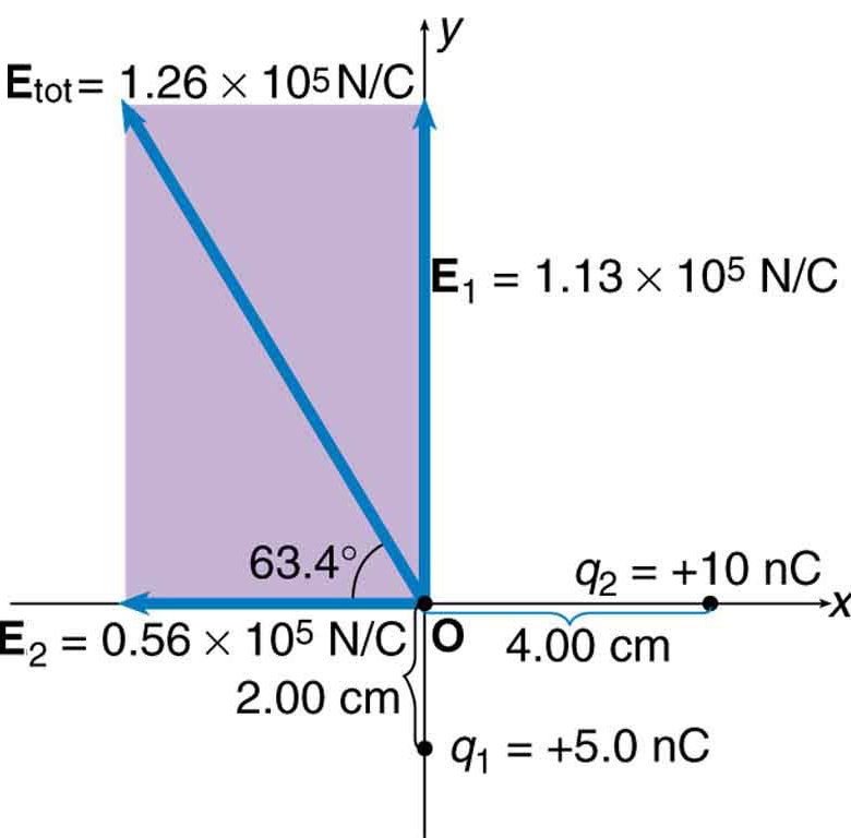
› Electric-Field-LinesPhysics Tutorial: Electric Field Lines The diagram above shows that the magnitude and direction of the electric field at each location is simply the vector sum of the electric field vectors for each individual charge. If more locations are selected and the process of drawing E A , E B and E net is repeated, then the electric field strength and direction at a multitude of locations ...
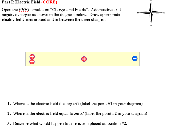
Solved Part I: Electric Field (CORE) Open the PHET | Chegg.com
› previous-year-question-papersMagnetic Effects of Electric Current Class 10 Important ... Aug 03, 2020 · Explain, the construction and working of an electric motor using a well labelled diagram. Answer: Electric motor converts electrical energy into mechanical energy. Principle: Electric Motor is based on the fact that a current carrying conductor placed perpendicular to the magnetic field experiences a force.
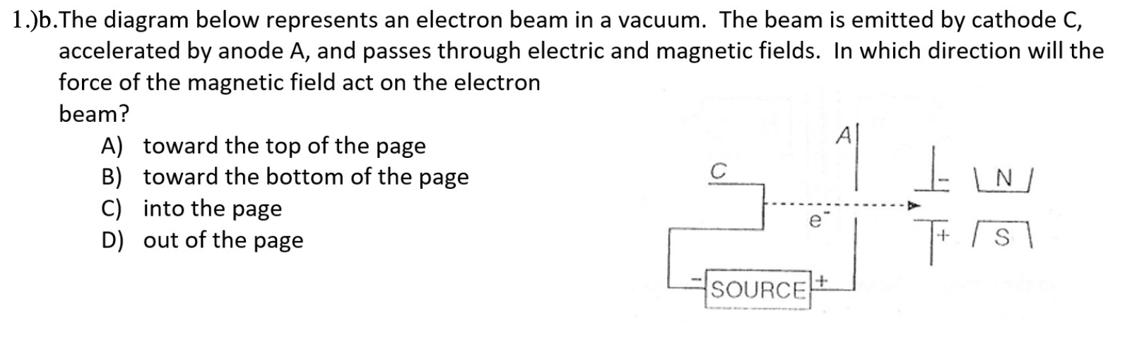
Solved 1.)a. The diagram below represents an electron moving ...
› articles › s41535/021/00418-2Field-induced multiple metal-insulator crossovers of ... Jan 25, 2022 · In the low-field regime below B th, ... H. CDW instability of electron gas in a strong magnetic field. ... C. C. Sliding-mode conductivity in NbSe 3: Observation of a threshold electric field and ...
Physics Tutorial: Electric Field Lines
Electrostatics-E_Field.pdf - Name Period Electrostatics-E ... e diagram below represents an electron within an electric eld between two parallel plates that are charged with a potential di erence of 40 volts.
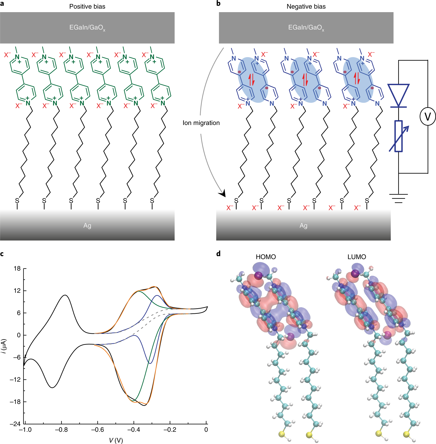
Electric-field-driven dual-functional molecular switches in ...
PDF Scanned Document - Bronx High School of Science A moving electron is deflected by two oppositely charged parallel plates, as shown in the diagram below. Electron The electric field between the plates is directed from (C) CtoD (D) DtoC (B) 13toA The diagram below represents a source of potential difference connected to two large, parallel metal plates separated by a distance of 4.0 x 10 meter.
r ;;;;;, I ;:T_T:l
PDF Nae Period Electrostatics-E Field - madison-schools.com 3. The diagram below represents an electron within an electric field between two parallel plates that are charged with a potential difference of 40 volts. If the magnitude of the electric force on the electron is 2.00 × 10⁻¹⁵ newton, the magnitude of the electric field strength between the charged plates is 1. 3.20 × 10⁻³⁴ N/C 2. 2.00 × 10 ...
Physics Tutorial: Electric Field Lines
Chemistry Final Exam Review - Part 3 - 2014-2015 - Quizlet Which electron dot diagram represents a molecule that has a polar covalent bond? B. ... The diagram below represents radiation passing through an electric field. The arrow labeled A most likely represents: D. Given the reaction. ... The diagram below represents a fission nuclear reactor. The arrows indicate the direction of flow of water.
Electric Field Lines – University Physics Volume 2
Zeeman Effect - an overview | ScienceDirect Topics Generic energy diagram for Zeeman splitting of angular momentum vectors in applied magnetic field. Normal Zeeman effect. The normal Zeeman effect is observed in systems with closed shells of electrons and arises due to lifting of the orbital degeneracy by an external magnetic field of moderate strength. It is manifest as equally spaced fine structure lines, for example, in …
Untitled
en.wikipedia.org › wiki › MemristorMemristor - Wikipedia A memristor (/ ˈ m ɛ m r ɪ s t ər /; a portmanteau of memory resistor) is a non-linear two-terminal electrical component relating electric charge and magnetic flux linkage.It was described and named in 1971 by Leon Chua, completing a theoretical quartet of fundamental electrical components which comprises also the resistor, capacitor and inductor.
Test Review Chapter 1
Test Review Chapter 1
1. The diagram below represents lines of magnetic flux
Electrostatics-E Field
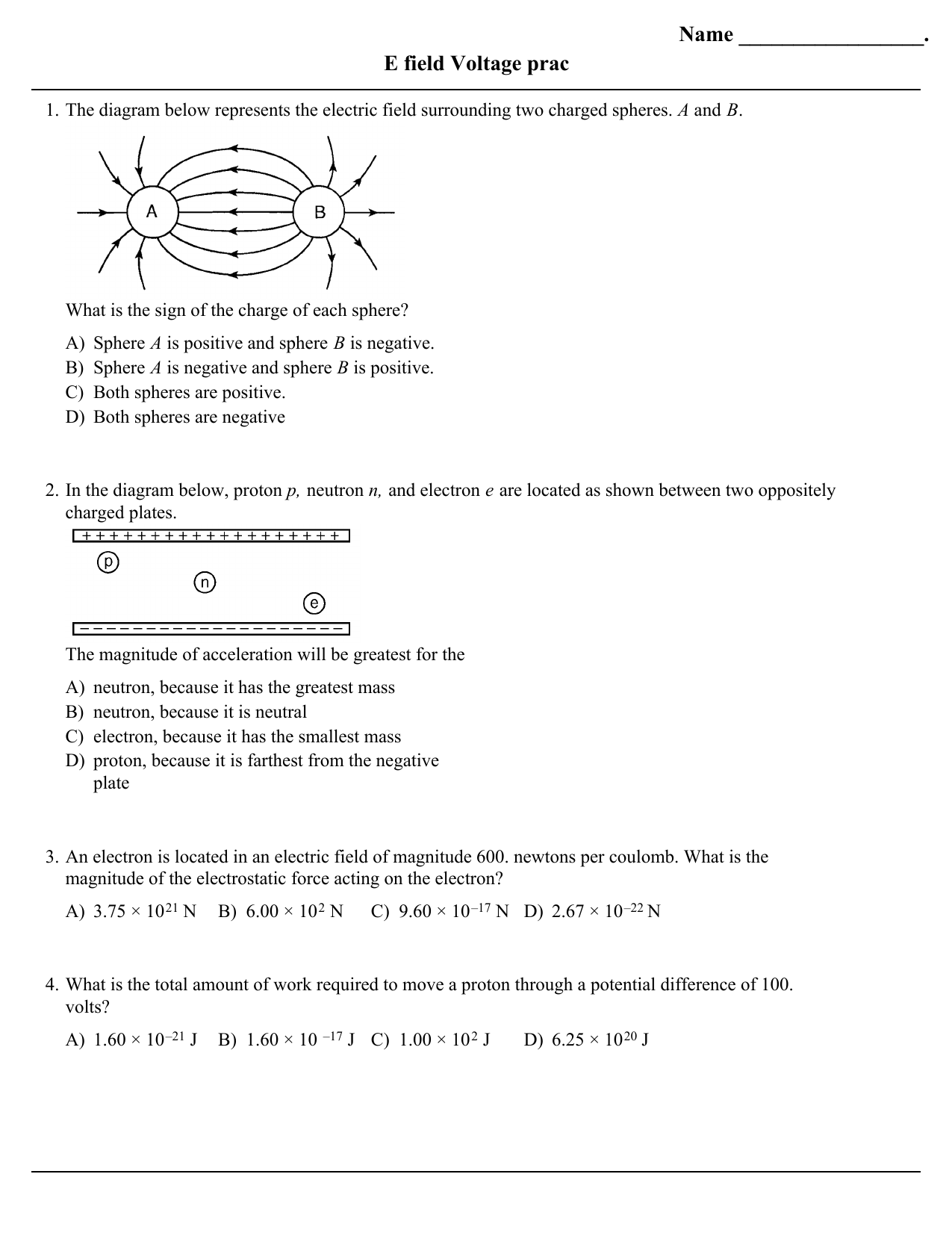
Name . E field Voltage prac
Electricity & Magnetism

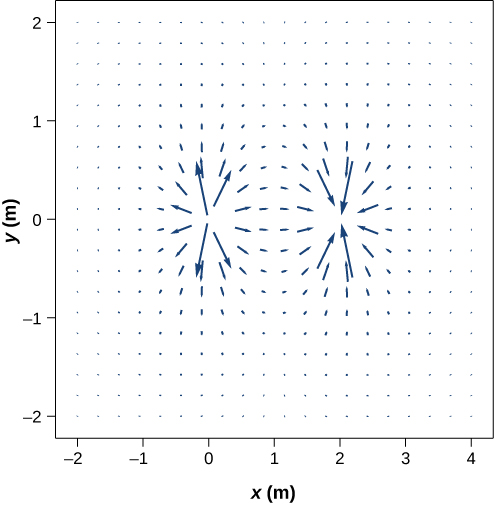
The diagram below represents the electric field in the region ...

An electron accelerates from rest through a uniform electric ...
PPT - Electrostatics Review PowerPoint Presentation, free ...
Electric Field Lines: Multiple Charges | Physics

9.3 Electric field | Electrostatics | Siyavula
Solved point charge and the distance, r, from the point ...

Electrostatics This is where the answers are located. - ppt ...
Electricity & Magnetism
Wizard Test Maker - Physics2010
Solved 1.)a. The diagram below represents an electron moving ...

9.3 Electric field | Electrostatics | Siyavula
electricity | Definition, Facts, & Types | Britannica
Name: Electric Fields Lecture Worksheet 1) How much ...
Test Review Chapter 1
AP Physics 2 Student Sample Responses to Question 4 - 2017 Exam

PhysicsLAB: June 2018, Part 2
Physics Week 2(Sem. 2)

Electric field direction (video) | Khan Academy
0 Response to "38 the diagram below represents an electron within an electric field"
Post a Comment