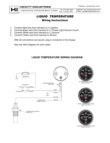
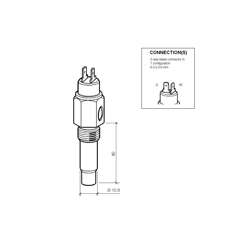
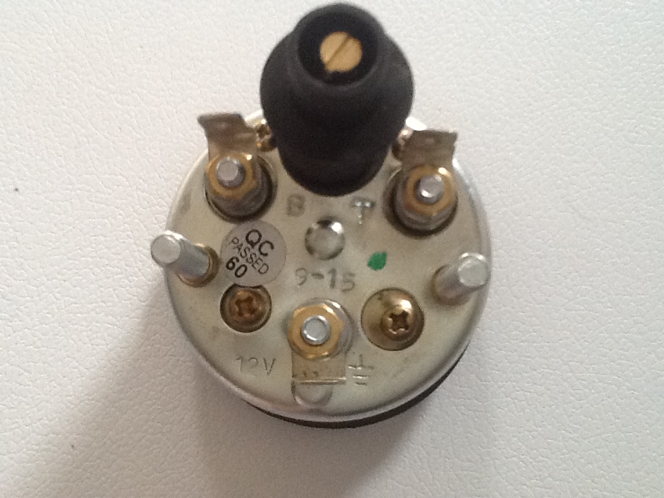
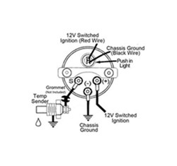
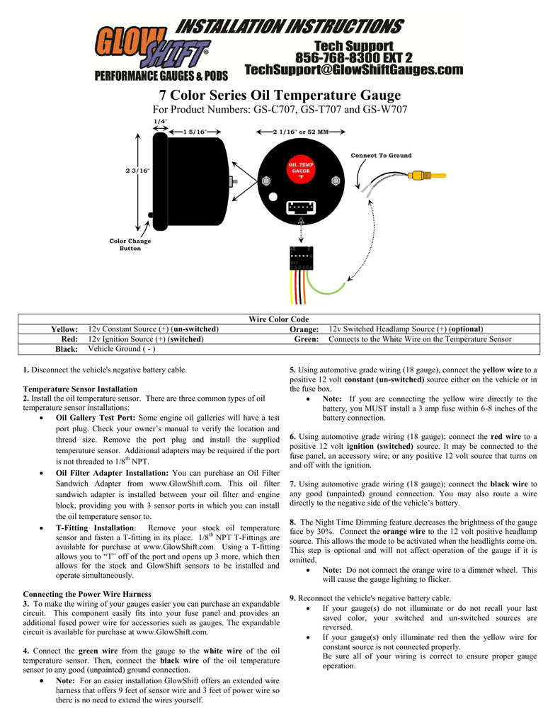
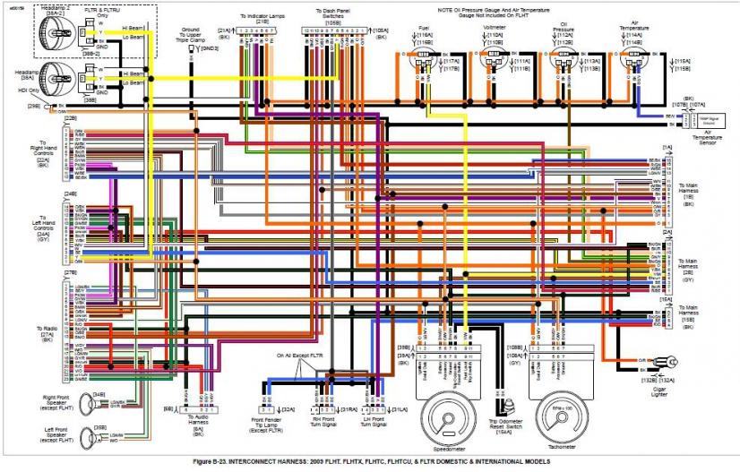
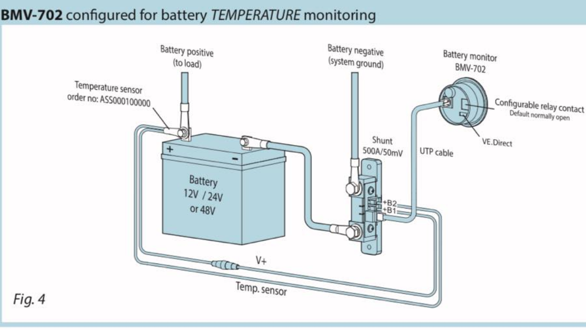
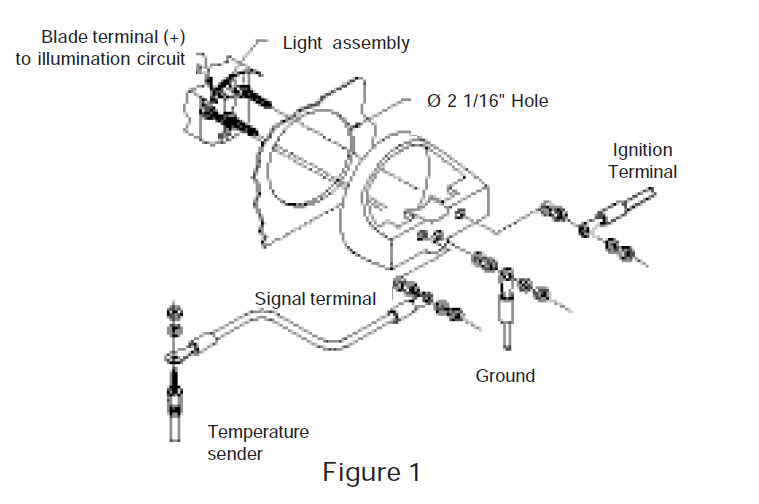
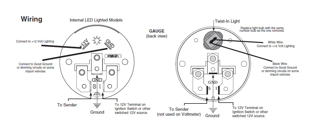
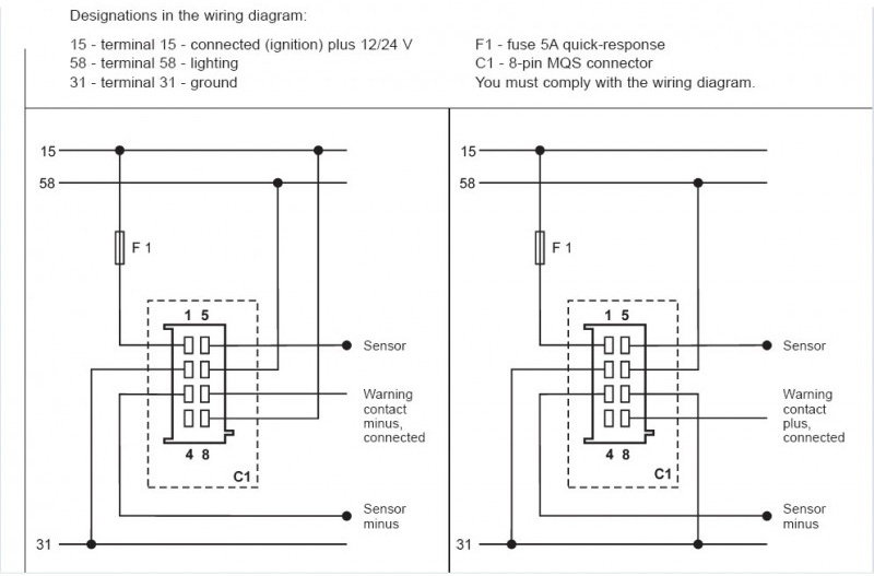
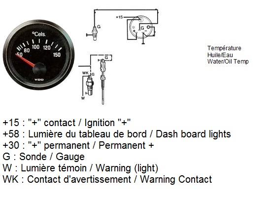
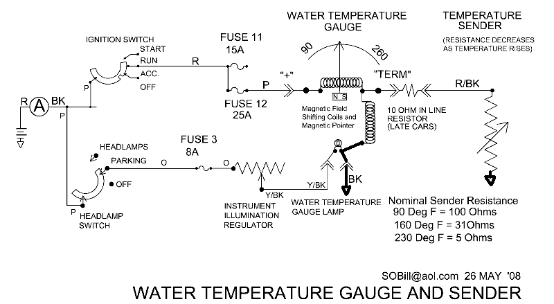
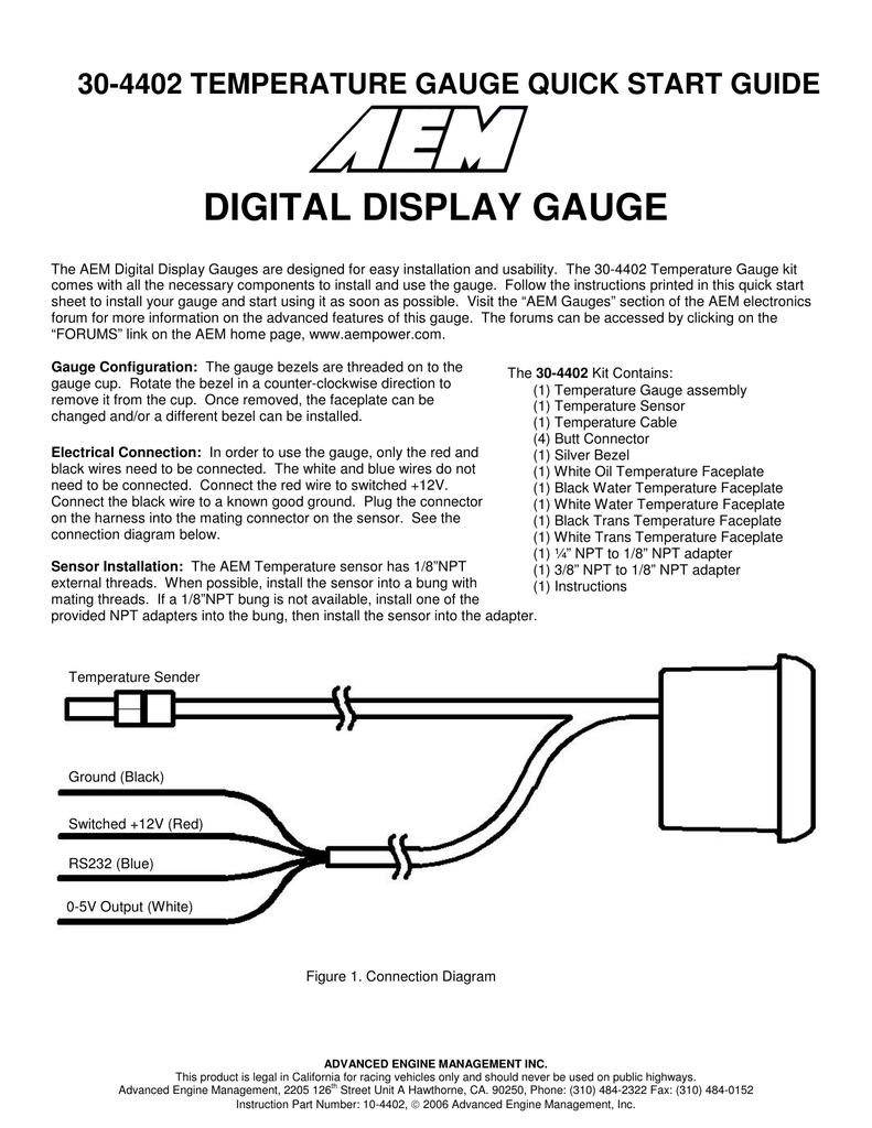
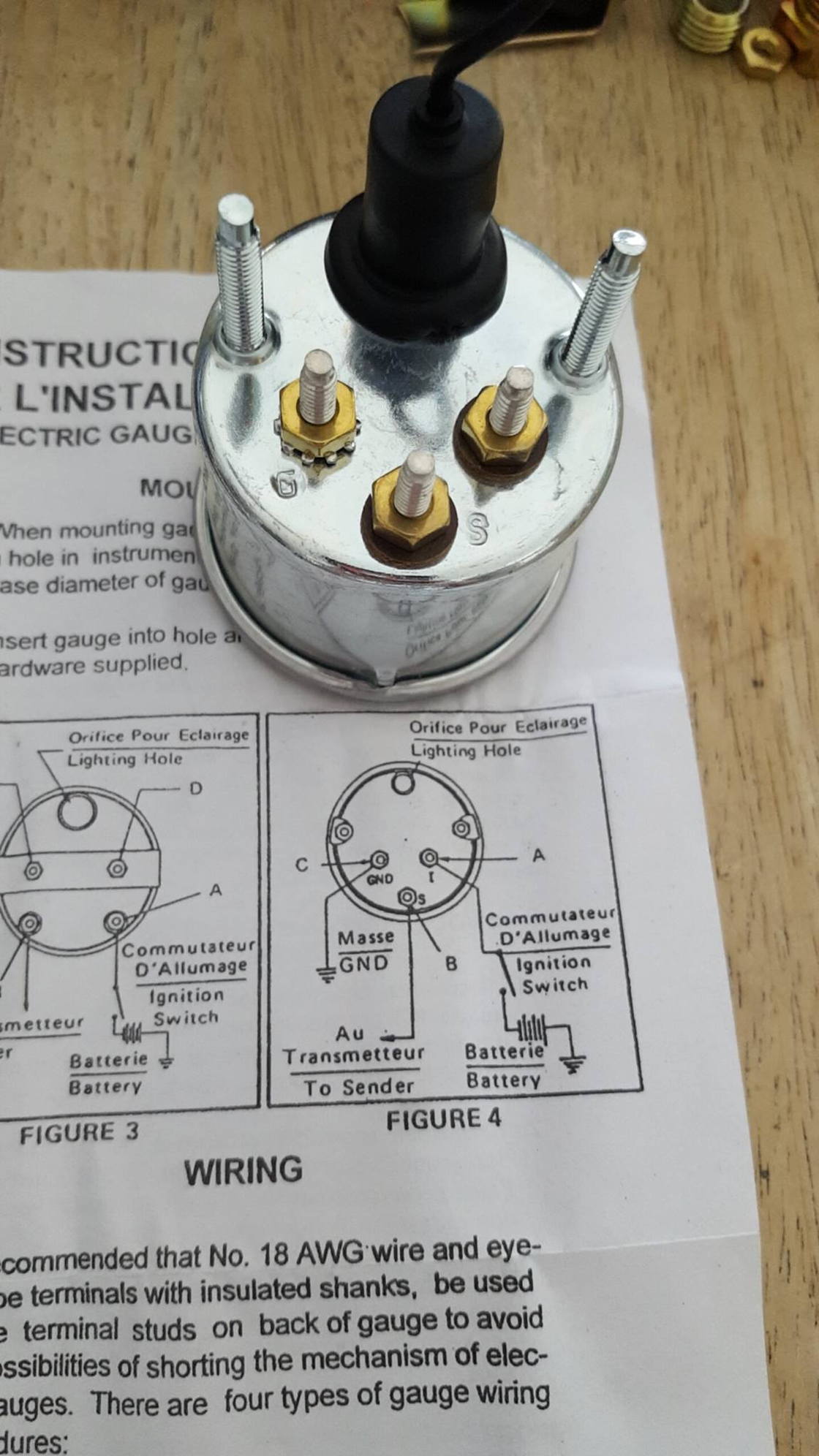
39 temperature gauge wiring diagram
PDF WATER TEMPERATURE - SAAS Automotive Wiring Diagram Ignition harness / Fuse box Red Ignition 12V+ Green Sensor input-Ignition harness / Fuse box Water temp sender output (red wire of sender) SAAS Automotive PTY LTD Colour change button Note: Colour change button is on the front for Series II gauges. Battery 12V+ Ground 12V-Ignition 12V+ Illumination 12V+ Mounting studs for U bracket. Vdo Water Temp Gauge Wiring Diagram the sender body, or backwards, the fuel gauge will read "FULL" when the temperature sender Refer to the wiring diagram, Diagram G. Wire gauges in series from a positive (+) Temperature: Needle to the temperature of the engine water.Using the expertise we've gained in developing specialized solutions for many of the world's leading manufacturers, we offer a large portfolio of pressure and temperature sensors that we manufacture our sensors in our own ISO and TSO registered facilities ...
wiring for temp & oil gauge - Morris Minor Owners Club Here's a wiring diagram for a typical Smiths type temperature gauge: ... lation.gif Note, the voltage stabilizer is fitted to the back of the speedometer in Minors. It is necessary to give a regulated 10V output, else the gauge(s) would go haywire as the battery charges and discharges.
Temperature gauge wiring diagram
Vdo Gauges Wiring Diagram Wiring Diagram Diagrams Darren Criss Gauge together with Sunpro Gauges Wiring Diagram also Vdo Gauge Wiring Diagram additionally On A 12 Volt Gauge Wiring Diagram For Vw together with Wiring Diagram For Auto Meter Gauge.. View wiring diagrams and schematics for hundreds of popular boats including Lowe, Larson, Alumacraft, Lund, and others. Vdo Gauges Wiring Diagrams - Page 3 - Wiring Diagram And Schematics vdo marine fuel gauge wiring diagram best of gauge sending. Vdo Water Temperature Gauge Wiring Diagram - Wiring Diagram Engine temperature directly affects combustion and moving internal parts. Use is restricted to. The digidash 2 lite is for road and track day use. The dd2 lite is a stand alone system supplied with its own set of sensors including. 1200c water temperature gauge use with vdo sender 24v 250 spade connection learn more cockpit international 2000c ... PDF UNIVERSAL WIRING HARNESS - Wiring Wizard location on gauge. Dk Blue Oil sender wire Connect to the 'SENDER' location on gauge. Tan Gas sender wire Connect to the 'SENDER' location on gauge. White Tach sender wire Connect to the 'SENDER' location on gauge. (-) Black Ground Connect to each gauge (ground location) as shown in diagram.
Temperature gauge wiring diagram. General Motors temperature gauge troubleshooting ... Remove the wire from the temperature-sending unit located on the engine (typically a dark green wire). Then connect the wire to a good ground. You can do this by using a jumper wire. Check the gauge, if the needle points to "Hot", replace the sending unit. If the needle does not move, remove the same dark green wire from back of the gauge ... Wiring Diagrams - Classic Instruments Wiring Diagrams. 01 Six Gauge Set Wiring Diagram 11/10/09. 01 Six Gauge Set Wiring Diagram 5/9/19. Six Gauge Set Wiring Diagram SNWH03 . All-American 3200/6400 Package Guide Rev 2/27/13. Download 3200 Wiring Instructions Rev 2/7/13. Download 6400 Wiring Instructions Rev 2/7/13 . Senders . SN11 Low Volt Light Rev 7/12/12 Troubleshooting Oil Pressure and Water Temperature Gauges ... There are a several checks you can perform to verify the gauges in your instrument cluster are working correctly. These can be helpful if you're trying to de... Autometer Water Temp Gauge Wiring Diagram MRC1 · MRC1 - Negative Coil Trigger Diagram · Nitrous Staging Diagram. is beneficial to add a T-fitting to install your new gauge and to keep the warning light operational. A. Water Temp: Install temperature sender (included). Instructions for: Temperature 2 1/16" Spek Pro Professional Racing Gauge .
Gauge Wiring Diagrams - ETB Instruments 52mm Water & Oil Temperature, Oil Pressure, Fuel Gauge, Voltmeter and Capacitive Advance Clock - Wiring Diagram: 83kb: ETB Fuel Level Sensor (Float-arm type) - Notes on Fitting: 159kb Oil Temperature Gauge Schematic Circuit Diagram Here are the specifications we set for the temperature gauge we wanted to build: • no moving parts (so no meter movement), as scooters vibrate a lot!; • as cheap as possible (around £12); • robust measuring transducer (avoid NTC thermistors and other 'exotic' sensors); temperature range 50-140 °C. (122 - 291 °F); • audible ... Fuel and Temperature Gauge Problems -- First Generation ... The possible causes for the malfunctioning gauges are: 1) a break in the wire from the gauge to the sending unit, 2) a bad sending unit, 3) a bad ground at the sending unit, or 4) the gauge itself is bad. To diagnose the fuel gauge, here is what I would do. Locate where the rear wiring harness, (the one from the tail lights) meets the main harness. VDO Documentation - VDO Marine Gauges VDO Resitive Gauge wiring Instructions - 2009; Veratron Flex Gauge 52mm NMEA2000 12/24v; ViewLine 52mm Wiring Diagram (2014) Viewline Level Gauges 12/24 Volt (2011) Viewline Level Gauges 52mm (2008) Viewline Pitot Speedometer / Level Gauge (2011) Viewline Pitot Speedometer/Fuel Gauge 110mm (2011) Viewline Pitot Speedometer/Fuel Gauge 110mm (2013)
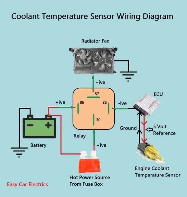
1, 2, & 3 Wire Coolant Temperature Sensor Wiring Diagram 3 Wire Coolant Temperature Sensor Wiring Diagram The two wires, a "5-volt reference", and a "ground wire" go to the ECU, and the third wire "Earth Signal Wire for Temperature Gauge" goes to the cluster-mounted temperature gauge by providing an earth signal to the temperature gauge. Temperature Gauge Wiring Diagram | Electrical diagram ... Temperature Gauge Wiring Diagram. Find this Pin and more on Boat by frans. Electrical Switch Wiring. Light Switch Wiring. Electrical Circuit Diagram. Trailer Light Wiring. Trailer Wiring Diagram. Off Grid Solar Power. Solar Power System. Vdo Water Temp Gauge Wiring Diagram - schematron.org on Vdo Water Temp Gauge Wiring Diagram. I. Installing the VDO Universal Temperature Sender Proper Wiring Between Gauge and Temperature Sender. 3. connected to the gauge (see Diagram B). 5. sender since the sender tip or bulb will not be immersed in the water flow. VDO Wiring Diagrams - Diagram will open in a new window. Racetech Gauges Wiring Diagram - schematron.org Also check behind the mounting location for any wiring or components before drilling. Fig 1. Gauge Wiring Diagram. Table 1. Wiring Summary. Color. RACETECH-LOGO-GREEN The Racetech electrical water temperature gauge is manufactured specifically for competition use having Instruction Manual. Electrical Gauges
PDF FLC Temperature Gauge - VDO - Global Website Temperature gauge, pressure gauge, rudder angel gauge, trim gauge, fuel gauge, fresh water gauge for level-type sensor TU00-0752-5207102 1-6 4 Technische Änderungen vorbehalten - Technical details subject to change TU00-0752-5207102 GB 12 Use the following connector to connect the instrument: Connector set, 8-pin - A2C59510850
Smiths Water Temperature Gauge Wiring Diagram Smiths water temperature gauge wiring diagram. 2500f1200c water temperature gauge use with vdo sender 12v 250 spade connection learn more cockpit international 1200c water temperature gauge use with vdo sender 24v 250 spade connection. Engine temperature directly affects combustion and moving internal parts.
2 Wire Temp Sensor Coolant Temperature Sensor Wiring ... 1993 1995 Iat And Ect Sensor Wiring Diagram Jeep 4 0l. 2 wire temp sensor coolant temperature sensor wiring diagram. 800 x 600 px source. You will need a test light and voltmeter to do some testing if. This 2 wire sensor Figures 1 and 2 is checking metal temperature and is used to infer coolant temperature. The diagram below shows the typical ...
Glowshift Trans Temp Gauge Wiring Diagram Glowshift Trans Temp Gauge Wiring Diagram. Glowshift's transmission temperature gauges are among some of the highest quality available to "T" into your Transmission Cooler Line for an effortless install. I have this gauge as well as a volt gauge and a water temp gauge mounted in .. The wiring diagram is easy to follow, but the instructions weren't ...
SOLVED: Temp gauge wiring diagram - Fixya According to the wiring diagram, the wire for the temp gauge is green, and the wires for the temp sensor for the computer are yellow and black. Read full answer. Aug 24, 2012 • 1990 GMC Sierra. 0 helpful. 1 answer. Temp gauge is not working, so Auto transmission won't shift to Overdrive (4th). Replaced a temp sending unit, but didn't fix it.
PDF 0 515 012 123 -- Electric Gauges - VDO Instruments Temperature, Pressure or Fuel Gauge (2⁵⁄₈" [66 mm] diameter) 1 2. Lamp Socket (Push in, wedge-type) 1 3. Light Bulb (12-volt / G.E. #158 or equivalent) 1 4. VDO Spin-Lok™ Clamp or mounting bracket 1 5. Installation Instructions 1 CAUTION: Read these instructions thoroughly before making installation. Do not deviate from assembly or wiring instructions.
PDF 3.0 3.0 Installation Instructions Electrical Gauges/Kits ... NOTE: Wire for gauge lights must be purchased separately. Use size 18-20 AWG stranded copper wire. 2. Splice the RED or WHITE wire from the gauge light(s) into the vehicle's lighting circuit, between the dimmer control switch and the dash lights (consult the vehi-cle's service manual for proper wire). 3 GAUGE LIGHT INSTALLATION AND CONNECTION3.
Temperature Gauge Wiring Diagram | autocardesign Temperature Gauge Wiring Diagram - wiring diagram is a simplified all right pictorial representation of an electrical circuit. It shows the components of the circuit as simplified shapes, and the aptitude and signal associates amid the devices.
PDF Auto Meter Gauges Installation Instructions 2. Route 18-gage wire through firewall. If a new hole is drilled in the firewall a grommet is recommended. Connect one end to . terminal post on temperature sender, and opposite end to sender (S) terminal on back of gauge. 3. Route 18-gage wire from center terminal GND (-) on back of gauge to good ground near sender. 4.
How to Wire a Temperature Gauge - It Still Runs Measure out a length of 14-gauge wire and run the end of the wire through a grommet on the firewall underneath the dashboard. Pull the wire through from the engine compartment. Route the wire until you reach the sensor position.
PDF UNIVERSAL WIRING HARNESS - Wiring Wizard location on gauge. Dk Blue Oil sender wire Connect to the 'SENDER' location on gauge. Tan Gas sender wire Connect to the 'SENDER' location on gauge. White Tach sender wire Connect to the 'SENDER' location on gauge. (-) Black Ground Connect to each gauge (ground location) as shown in diagram.
Vdo Water Temperature Gauge Wiring Diagram - Wiring Diagram Engine temperature directly affects combustion and moving internal parts. Use is restricted to. The digidash 2 lite is for road and track day use. The dd2 lite is a stand alone system supplied with its own set of sensors including. 1200c water temperature gauge use with vdo sender 24v 250 spade connection learn more cockpit international 2000c ...
Vdo Gauges Wiring Diagram Wiring Diagram Diagrams Darren Criss Gauge together with Sunpro Gauges Wiring Diagram also Vdo Gauge Wiring Diagram additionally On A 12 Volt Gauge Wiring Diagram For Vw together with Wiring Diagram For Auto Meter Gauge.. View wiring diagrams and schematics for hundreds of popular boats including Lowe, Larson, Alumacraft, Lund, and others. Vdo Gauges Wiring Diagrams - Page 3 - Wiring Diagram And Schematics vdo marine fuel gauge wiring diagram best of gauge sending.











0 Response to "39 temperature gauge wiring diagram"
Post a Comment