40 shear moment diagram examples
Shear, Moment, and Deformation Relationships in... | Civil Engineering X The relationship between shear and moment identified in Eq. (3.72), that is, V = dM/dx, indicates that the shear force at a section is the rate of change of For example, the internal forces at the quarter span of the uniformly loaded beam in Fig. 3.31 may be determined from the free-body diagram in Fig. Drawing Shear and Moment Diagrams Example- Mechanics of... This is a detailed example of shear and moment diagrams, i recommend skipping around to the sections shown below if you already have a feel for the subject...
Shear Forces and Bending Moments in Beams [EXAMPLES] Moment diagrams. [examples]. • Equilibrium Method for V and M Diagrams • Semi-graphical Method for V and M Diagrams. COSC321Haque PDF_C8_b (Shear Forces and Bending Moments in Beams).

Shear moment diagram examples
PDF Design Aid 6 Beam Design Formulas with Shear and Moment Diagrams Moment. DESIGN AID No. 6. American Forest & Paper. Association. Beam formulas with shear and moment. Diagrams. Figures 1 through 32 provide a series of shear and moment diagrams with accompanying formulas for design of beams under various static loading conditions. PDF statics.dvi | Statics of Bending: Shear and Bending Moment Diagrams The moment diagram is now parabolic, always being one order higher than the shear diagram. following shows how the moment equation of this example might be plotted, using the Heaviside function to provide the singularity. Shear and moment diagram - Wikipedia Shear and bending moment diagrams are analytical tools used in conjunction with structural analysis to help perform structural design by determining the value of shear force and bending moment at a given point of a structural element such as a beam.
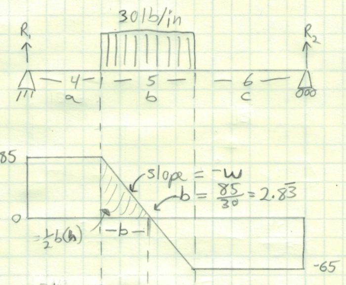
Shear moment diagram examples. Shear and Moment Diagrams | Strength of Materials Review at... Shear and Moment Diagrams Consider a simple beam shown of length L that carries a uniform load of w (N/m) throughout its length and is held in equilibrium by reactions R 1 and R 2 . Assume that the beam is cut at point C a distance of x from he left support and the portion of the beam to the right of. Solved: Plot shear force and moments in Mathcad - PTC Community We are learning shear force and moments and we are drawing them by hand. I understand all the calculations and how to draw shear force and bending moment diagrams but the bonus question on our assignment is to plot the diagram below in Mathcad using x-y graphs. Shear Force & Bending Moment Diagram of Simply Supported Beam Shear force and bending moment diagram of simply supported beam can be drawn by first calculating value of shear force and bending moment. Shear force and bending moment values are calculated at supports and at points where load varies. Simply Supported Beam with Point Load Example. Shear Force and Bending Moment - Materials - Engineering Reference... Shear Forces occurs when two parallel forces act out of alignment with each other. For example, in a large boiler made from sections of sheet metal plate It can be seen from the examples that "peaks" in the bending moment diagram frequently occur at concentrated loads or reactions, and these are not...
Shear and Moment Diagrams Shear and Moment Diagrams. Transverse loading refers to forces that are perpendicular to a structure's long axis. The best way to recall these diagrams is to work through an example. Begin with this cantilevered beam - from here you can progress through more complicated loadings. Bending moment and shear force diagram of a cantilever beam Bending moment diagram and shear force diagram of a cantilever beam having point load at the end,several point load,u.d.l. over whole ,from support to A shear force diagram is the graphical representation of the variation of shear force along the length of the beam and is abbreviated as S.F.D. Axial, Shear & Moment Diagrams - StructNotes | Example 8 Axial, shear, and bending moment diagrams (AFD, SFD, and BMD) show the internal forces and moments along a structural member. They help determine the material, size, and type of a member given a set of loads it can support without structural failure. Keeping a consistent sign convention is... Shear And Moment Diagrams Examples - Source Code Usage... What is Shear And Bending Moment Diagrams For Frames Examples (As required) Use the results from each member to draw overall axial force, shear force and bending moment diagrams for the entire frame structure. The bending moment of the "short" column is four times higher than the...
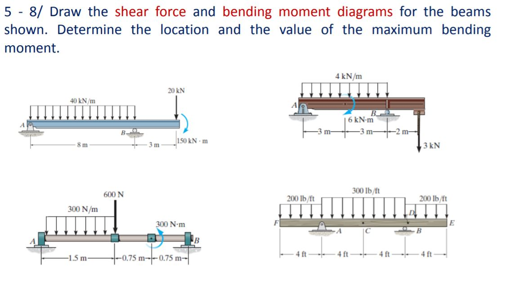
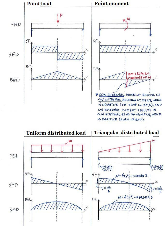
Shear Force and Bending Moment Diagrams - Wikiversity 3 Basic bending moment diagram. 4 Point moments. 5 Uniformly Distributed Load (UDL). 5.1 Shear force diagram. 5.2 Bending moment diagram. The idea of shear force might seem odd, maybe this example will help clarify. Imagine pushing an object along a kitchen table, with a 10N force. How to Calculate and Draw Shear and Bending Moment Diagrams To complete a shear force and bending moment diagram neatly you will need the following materials. Step 12: Video. - Here is a video on how to carry out an example shear and bending moment diagrams along with displacement. Mechanics of Materials Chapter 4 Shear and Moment In Beams ‰The bending moment and shear force diagrams of the beam are composites of the V and M diagrams of the segments. These diagrams are usually discontinuous, or have discontinuous slopes. At the end-points of the segments due to discontinuities in loading. PDF Shear Forces and Shear-Force and Bending-Moment Diagrams. When solving the problems for Section 4.5, draw the shear-force and bending-moment diagrams approximately to scale and label all critical ordinates, including the maximum and minimum values.
Shear Force Diagram - an overview | ScienceDirect Topics
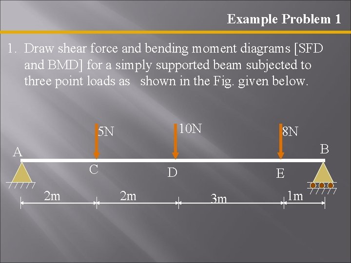
PDF Microsoft PowerPoint - CE 382 L6 - Shear and Moment Diagrams Shear and bending moment diagrams depict the variation of these quantities along the length of the member. Proceeding from one end of the member to the other, sections are Shear and Bending Moment Diagrams. 8. 2. Principle of Superposition. Example Problem Shear and Moment Diagrams.
Determining the Shear Force and Bending Moment Equations of ...
PDF Slide 1 | M = M0 + (area under the shear diagram from x0 to x) Slope of the moment curve = Shear Force. Both equations not applicable at the point of loading because of discontinuity produced by the abrupt change in If there is no externally applied moment M0 at x0 = 0, total moment at any section equals the area under the shear diagram up to that section.
Shear Force and Bending Moment Diagram Calculator ...
Statics eBook: Shear and Moment Diagrams I | Example Example. Draw the shear and moment diagram for the beam shown in figure. The resulting graphics are called the shear diagram and moment diagram. Since the same x was used for all three sections, the each equation for each section can be easily plotted as shown at the left.

Shear force and bending moment diagram and examples - PIGSO ...
Shear Force and Bending Moment diagram for Simple supported beam Bending moment diagram will be a straight line when there is point load and it is parabolic when there is uniformly distributed load (udl). You can visit the following links of solved examples on Bending moment and shear force calculations and plotting of diagrams.
Example - Equation approach | C5.3 Shear Force and Bending ...
Figure 4.12: Example Frame Member BC Axial, Shear and Moment Now the axial moment, shear force and bending moment diagrams may be found by solving each member as if it was a separate beam (see see Section 4.3). Figure 4.9: Example Frame Free Body Diagram. Starting with the moment equilibrium about point A to find the vertical reaction at D ($D_y$)

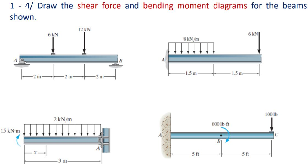
1. Draw a shear force and bending moment diagram for the beam ...
Chapter 8. Shear Force and Bending Moment Diagrams for Uniformly... 1 hapter 8 Shear Force and ending Moment Diagrams for Uniformly Distributed Loads. 8.1 Introduction In Unit 4 we saw how to calculate moments for 9 More Examples Involving Uniformly Distributed Loads Draw the shear force and bending moment diagrams for each of the beams shown in Fig.

Shear Force and Bending Moment - Materials - Engineering ...
The Ultimate Guide to Shear and Moment Diagrams Shear force and bending moment diagrams tell us about the underlying state of stress in the structure. So naturally they're the starting point in any design process. Consider the shear force between A and D for example; it's constant, which means the slope of the bending moment diagram is also constant...

Draw the shear and moment diagrams for the beam. | Study.com
PDF Shear and Bending Moment Diagrams Consider the following example. Load, Shear Force and Bending Moment Relationships: Consider the following beam segment with a uniformly distributed load with load intensity q. Note that distributed loads are Causes an abrupt change in bending moment. Shear and Bending Moment Diagrams
Shear and Moment Diagram Example 3 - Mechanics of Materials
Shear And Moment Diagram Examples - Wiring Diagram Database Shear and moment diagrams for frames example. Another example of drawing shear and moment diagrams graphically for beam. Consider a simple beam shown of length l that carries a uniform load of w nm throughout its length and is held in equilibrium by reactions r1 and r2.
shear force and bending moment diagram - ppt download
mechanical engineering - Drawing the shear and bending moment... Here is one of the questions that I am stuck at: Find the shear and bending moment diagram of the following rigid frame: I have tried working out the forces but they seem to be wrong after To get the vertical reactions we need to calculate the moment around a given point, which must be equal to zero.
Determining the Shear Force and Bending Moment Equations of ...
Shear forces and bending moments diagrams Note that, while the shear force diagrams appeared to be mirrored images (flipped horizontally), the bending moment diagram is not affected. Additionally, the most important result of this analysis, illustrates that maximum shear force and bending moment magnitudes will always be the same.

SA07U: Shear & Moment Equations
Indeterminate Shear/Moment Diagrams For my last Shear and Moment diagram example, I'll look at a frame. A frame is a structure that has ridigidly connected members that allow for The shear/moment diagrams for indeterminate structures function the same as determinate structures. In most cases you will know the end forces for a section...

What is a shear force and bending moment diagram in ...
Shear and moment diagram - Wikipedia Shear and bending moment diagrams are analytical tools used in conjunction with structural analysis to help perform structural design by determining the value of shear force and bending moment at a given point of a structural element such as a beam.
Example - Direct method | C5.3 Shear Force and Bending Moment ...
PDF statics.dvi | Statics of Bending: Shear and Bending Moment Diagrams The moment diagram is now parabolic, always being one order higher than the shear diagram. following shows how the moment equation of this example might be plotted, using the Heaviside function to provide the singularity.
The Ultimate Guide to Shear and Moment Diagrams ...
PDF Design Aid 6 Beam Design Formulas with Shear and Moment Diagrams Moment. DESIGN AID No. 6. American Forest & Paper. Association. Beam formulas with shear and moment. Diagrams. Figures 1 through 32 provide a series of shear and moment diagrams with accompanying formulas for design of beams under various static loading conditions.

Shear and moment diagram - Wikipedia

Shear moment diagram example
Shear Moment Diagrams: The Best Guide to Using Them ...
Solved For the all examples. Draw the shear force and the ...

Shear-force and bending-moment diagrams along the base of the ...
Solved Draw the shear force diagrams and the bending moment ...
Shear Force and Bending Moment Diagrams SFD BMD
Shear force and bending moment diagram practice problem #7
Exercise: Shear Force & Bending Moment Diagrams (Solution ...

Learn How To Draw Shear Force And Bending Moment Diagrams ...
Shear Load and Bending Moment Diagrams

Moment Diagrams: Examples

Shear force and bending moment diagram and examples - PIGSO ...
How to Draw Shear Force & Bending Moment Diagram | Simply ...
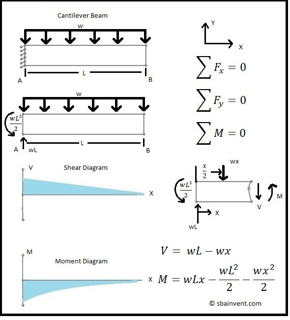
Shear and Moment Diagrams - S.B.A. Invent

Solidworks Tutorial of Shear Force and Bending Moment Diagram ...

Bending Shear and Moment Diagram Graphical method to
Moment Diagrams: Examples
Theory | C4.1 Shear Force and Bending Moment Diagrams | Solid ...

Moment Diagrams Constructed by the Method of Superposition ...
Mechanics of Materials Chapter 4 Shear and Moment In Beams

Drawing Shear Force, Bending Moment Diagram » File Exchange ...
6.2 Shear/Moment Diagrams – Engineering Mechanics: Statics

Shear force and bending moment diagram practice problem #2
6.2 Shear/Moment Diagrams – Engineering Mechanics: Statics
0 Response to "40 shear moment diagram examples"
Post a Comment