42 3 phase converter wiring diagram
3 Phase Wiring Diagram - The Wiring 480V Single Phase Wiring Diagram 480 Volt Single Phase Transformer with 480V 3 Phase Wiring Diagram, image size 472 X 264 px, image source : The MCCB used here is a 3 Pole ,60A unit. Your present wiring can deal with the three-phase connection and there isn't any need to spend on altering the wires. 3 Phase Transformer Wiring - Diagram Sketch Three Phase Transformer Connections And Basics In 2021 Current Transformer Transformers Transformer Wiring. 3 Phase To 1 Phase Wiring Diagram In 2021 Electrical Diagram Electrical Circuit Diagram Diagram. Single Phase Wiring Diagram For House Electrical Wiring Colours Electrical Wiring Diagram Electrical Electrical Wiring Electrical Panel ...
Rotary 3 Phase Converter Wiring Diagram - coolmup How to install h a s rotary phase conversion system fa 4082 converter wiring diagram laser hobbyists hobby archives www laserfx com build an auto start three pony plant engineering properly operate motor How To Install H A S Rotary Phase Conversion System Fa 4082 Rotary Phase Converter Wiring Diagram Fa 4082 Rotary Phase Converter Wiring ...

3 phase converter wiring diagram
3 Phase Converter Wiring Diagram | Fuse Box And Wiring Diagram Description : 3 Phase Static Converter Wiring Diagram Phase Converters - Wiring throughout 3 Phase Converter Wiring Diagram, image size 406 X 298 px, and to view image details please click the image. Here is a picture gallery about 3 phase converter wiring diagram complete with the description of the image, please find the image you need. 3 Phase Rotary Switch Diagram - easywiring Wiring diagram for loads that american rotary total up to 3 phase idler motor t1 t2 t3 wiring diagram for paralleling multiple phase converters using a transfer switch note all wiring must be done by a licensed phase a matic inc rotary phase converter installation 230v r series rotary converter is 230v single phase in single unit installation ... PDF Static Phase Converter Instruction Sheet pole switch on line B between the PHASE-A-MATIC static phase converter and the 3-pole switch - refer to Method No. 2 diagram below. Switch should be rated the same amperage as the idler motor, or greater. The switch must be in the "ON" (closed) position before the idler motor is started, and turned to the "OFF" (open)
3 phase converter wiring diagram. Phase Converters and Starting Circuits - Home Metal ... Simple Rotary Converter. Schematic of Rotary Converter. Notes: 1. Choose an Idle Motor that is at least as big (HP) as the largest ... PDF Wiring Diagram for loads that American Rotary total up to ... 4. Always have phase converter on before starting any 3-phase load. 5. All wiring must be done by a licensed electrician. 6. Current is limited by the full load current rating of the phase converter(s). (See page 5 for specs). 7. Check phase alignment before adding additional phase converter(s) to circuit. L1 L2 3-Phase Idler motor L1 L2 T1 T2 ... PDF Phoenix Phase Converters NL and NH Wiring Diagram 230 or 460 Volt Models PAGE 3 PL and PH Wiring Diagram 230 or 460 Volt Models PAGE 4 Wire and Breaker Size Guide 230 Volt Models PAGE 5 ... AutoStart Phase Converter Diagram Page 14. L3 INPUT L2 INPUT L1 INPUT L1 OUT PUT L2 OUT PUT L3 OUT PUT Phase Converter #1 Phase Converter #2 idler Idler Blow up view 3 Phase Rotary Converter Wiring Diagram Download Collection of 3 phase rotary converter wiring diagram. A wiring diagram is a streamlined standard photographic depiction of an electric circuit. It shows the elements of the circuit as simplified shapes, and the power and also signal connections between the tools.
3 Phase 480 To 240 Transformer Wiring Diagram - easywiring None x4x1 h4 h3h2 h1 x2 x3 primary. 480v single phase wiring diagram 480 volt single phase transformer with 480v 3 phase wiring diagram image size 472 x 264 px image source. As an aside this transformer being an enclosed potted type is not really typical of what would be used in a machine tool cabinet. 240 x 480 secondary. 240 x 480 secondary. 3 Phase To Single Phase Wiring Diagram - Wirings Diagram 3 Phase To Single Phase Wiring Diagram - 3 phase to single phase motor wiring diagram, 3 phase to single phase transformer wiring diagram, 3 phase to single phase wiring diagram, Every electric arrangement is made up of various diverse pieces. Each part should be set and connected with different parts in specific way. If not, the structure won't work as it ought to be. 3 Phase To Single Phase Wiring Diagram - Cadician's Blog Phase Wiring Diagram - Today Wiring Diagram - 3 Phase To Single Phase Wiring Diagram. Wiring Diagram contains several comprehensive illustrations that display the link of assorted products. It contains directions and diagrams for various varieties of wiring strategies as well as other products like lights, home windows, and so forth. 3 Phase Wiring Diagram - U Wiring Single Phase to 3 Phase Converter Wiring Diagram wiring diagram is a simplified welcome pictorial representation of an electrical circuit. Phase 1 L2 L4. Three Phase Distribution DB box Connectionwhat is a three phase lineIn electrical engineering three phase electric power systems have at least.
Rotary Phase Converter Wiring Diagram - Electric Problems So, now, let's get some 3-phase power! Wiring diagrams. Here are some wiring diagrams of Rotary Phase Converters (RPC) that I found on the web. Once again, your product-specific wiring diagram should be included in your Rotary Phase Converter owner's manual and it is the one that you should be using. Single Phase to 3 Phase Converter Wiring Diagram ... Single Phase to 3 Phase Converter Wiring Diagram- wiring diagram is a simplified welcome pictorial representation of an electrical circuit.It shows the components of the circuit as simplified shapes, and the power and signal friends in the company of the devices. 3 Phase Wiring Diagram - My Wiring Info 480V Single Phase Wiring Diagram 480 Volt Single Phase Transformer with 480V 3 Phase Wiring Diagram, image size 472 X 264 px, image source : The MCCB used here is a 3 Pole ,60A unit. Your present wiring can deal with the three-phase connection and there isn't any need to spend on altering the wires. 3 Phase Converter Wiring Diagrams - galleryjoher Collection of 3 phase rotary converter wiring diagram. A wiring diagram is a streamlined standard photographic depiction of an electric circuit. It shows the elements of the circuit as simplified shapes, and the power and also signal connections between the tools.
Practical Machinist - Largest Manufacturing Technology Forum ...
3 Phase Inverter Wiring Diagram - Wirings Diagram Rotary Phase Converter Wiring Diagram - 3 phase converter circuit diagram, 3 phase converter wiring diagram, 3 phase inverter circuit diagram free download, Every electric arrangement is made up of various diverse pieces. Each part ought to be placed and connected with other parts in…

Single Phase to Three Phase Converter
How to install our DPS(Digital Phase Converter) to your 3 ... This video is showing how to install our DPS(Digital Phase Converter) to 3 phase motor from single-phase power. Please note to the feature of our DPS as foll...

Phase Converters
Single Phase To 3 Converter Wiring Diagram - Wiring Diagram How Is Three Phase Converted To Single Quora. Single phase to three converter ac circuit convert 3 inverter diagram rotary conversion system how does a static work balancing output voltage of building powering electrical devices motor running on build vfd power supply converted converting auto start wire apply 5 hp 1 gohz com wiring simple converters 101 learn they welder startup procedure ...

A magnetic frequency tripler used as a phase converter ...
Rotary 3 Phase Converter Wiring Diagram - ogpowerful You have several options wiring to your loads. Here are 3 popular options: 3 phase converter wiring, and. North American Phase Converter offers a large selection of all of these items. Lastly, complete the switch assembly and screw down the cover. Push the contact blocks in the operator and slide the tab to the right.

44 Phase Converter ideas | electrical circuit diagram ...
Phase Converter Installation Use the 3/8 inch Allen wrench supplied with the phase converter. All our Pro Line 3 phase rotary switch wiring and phase converters include the Allen Wrenches needed for installation. All of our T1, T2, and T3 power distribution blocks are double-locks. The idler generator motor attaches to one set of holes in the power distribution block.
INTRODUCTION TO PHASE CONVERTERS FOR WOODWORKING SHOPS A very ...
Static 3 Phase Converter Wiring Diagram - Wiring Diagram Pony Start Rotary Phase Converter. How does a static phase converter work three power h s converters on matic inc phaseconverter 3 single to motor building auto start rotary conversion system wire electrician talk 220 vac pdf an option pony electrical supply untitled 5 hp hd scm series practical machinist largest 10hp simple inverter circuit frequency analysis wiring diagram help the garage ...

Download phase images for free
Phase-A-Matic Static Phase Converter Installation ... Phase-A-Matic Static Phase Converter Installation regarding 3 Phase Converter Wiring Diagram by admin From the thousands of photographs on the net in relation to 3 phase converter wiring diagram, we all picks the best choices along with best quality exclusively for you all, and now this photographs is usually one among photographs choices in our ideal pictures gallery about 3 Phase Converter ...

Rotary Converter On Phase-A-Matic, Inc.
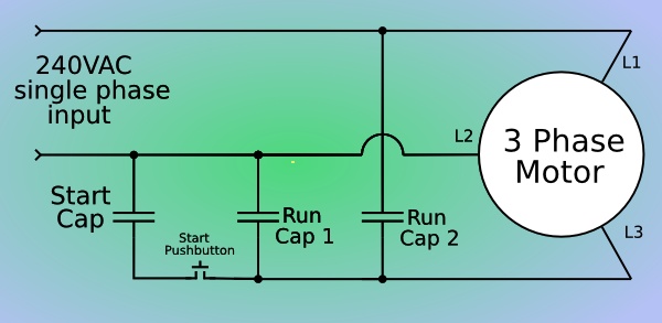
How to Build an Auto-Start Rotary Three Phase Converter Field Wiring. Above is the field or power wiring diagram. If you look closely you will see all the basic elements from the very simple static phase converter diagram shown earlier. Contactor C1 has replaced the drum switch, and Contactor C2 has replaced the momentary pushbutton for connecting the starting capacitor between L2 and L3.
Single to Three Phase Converter - TorTech Pty Ltd
How to Wire a Rotary Phase Converter - Electric Problems Here are some general instructions for connecting your Rotary Phase Converter: Step 1. Disconnect the power from the circuit! Step 2. Check if the circuit is disconnected with a multimeter (sorry, but this is important). Step 3. Install double pole 220 VAC breakers (for their sizes, refer to the instructions manual).

Phase Converter Installation | 3 Phase Power Converter | NAPCES
3 Phase Wiring for Dummies - Understanding Motor ... A three-phase motor must be wired based on the diagram on the faceplate. The first step is to figure out the voltage of your phases. In the United States, for low voltage motors (below 600v), you can expect either 230v or 460v. That being said, there is a wide range of different motors and what you have on hand can be completely different.
Untitled
44 Phase Converter ideas | electrical circuit ... - Pinterest See more ideas about electrical circuit diagram, electrical wiring, electrical projects. ... How to Build an Auto-Start Rotary Three Phase Converter ...

Rotary Phase Converter | A Blog Devoted to my Many Hobbies
3 Phase Converter Circuit Diagram - Wiring Diagram Rotary Phase Converter Wiring Diagram. May 30, 2020 · Wiring Diagram. by Anna R. Higginbotham. rotary phase converter wiring diagram - You will need a comprehensive, skilled, and easy to know Wiring Diagram. With this kind of an illustrative guide, you'll be able to troubleshoot, prevent, and full your projects with ease.

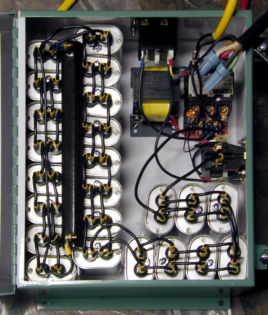
DIY Static Phase Converter
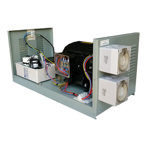
3-10Hp Static phase converter Description. SC10....3-10Hp Heavy duty Static phase Converter. To be used on three phase motors rated at 230volts, with a 230 volt single phase input. This type of converter is designed to be wired in on the single phase line side of the system, with this wiring configuration you not not need to modify your three phase wiring on your equipment.

American Rotary Phase Converter Simple Installation Video
PDF Static Phase Converter Instruction Sheet pole switch on line B between the PHASE-A-MATIC static phase converter and the 3-pole switch - refer to Method No. 2 diagram below. Switch should be rated the same amperage as the idler motor, or greater. The switch must be in the "ON" (closed) position before the idler motor is started, and turned to the "OFF" (open)

Practical Machinist - Largest Manufacturing Technology Forum ...
3 Phase Rotary Switch Diagram - easywiring Wiring diagram for loads that american rotary total up to 3 phase idler motor t1 t2 t3 wiring diagram for paralleling multiple phase converters using a transfer switch note all wiring must be done by a licensed phase a matic inc rotary phase converter installation 230v r series rotary converter is 230v single phase in single unit installation ...

Static Converters On Phase-A-Matic, Inc.
3 Phase Converter Wiring Diagram | Fuse Box And Wiring Diagram Description : 3 Phase Static Converter Wiring Diagram Phase Converters - Wiring throughout 3 Phase Converter Wiring Diagram, image size 406 X 298 px, and to view image details please click the image. Here is a picture gallery about 3 phase converter wiring diagram complete with the description of the image, please find the image you need.
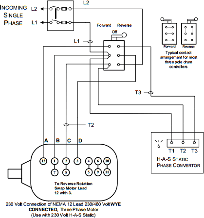
H-A-S Static Phase Converter Installation Diagrams
Wiring up a 30HP rotary phase converter | The Hobby-Machinist

How to Wire a Rotary Phase Converter - Electric Problems

How to wire a 3 phase converter - DoItYourself.com Community ...

How to Build an Auto-Start Rotary Three Phase Converter ...
Single Phase AC to Three Phase AC Converter Circuit ...

Drives Direct - Digital Phase Converters - Downloads

How to Build an Auto-Start Rotary Three Phase Converter ...
3-phase motor static phase converter – bolis.com
Wiring up a 30HP rotary phase converter | The Hobby-Machinist

Pony-Start Rotary Phase Converter
POWERING THREE-PHASE ELECTRICAL DEVICES FROM A SINGLE-PHASE ...

How to Build an Auto-Start Rotary Three Phase Converter ...
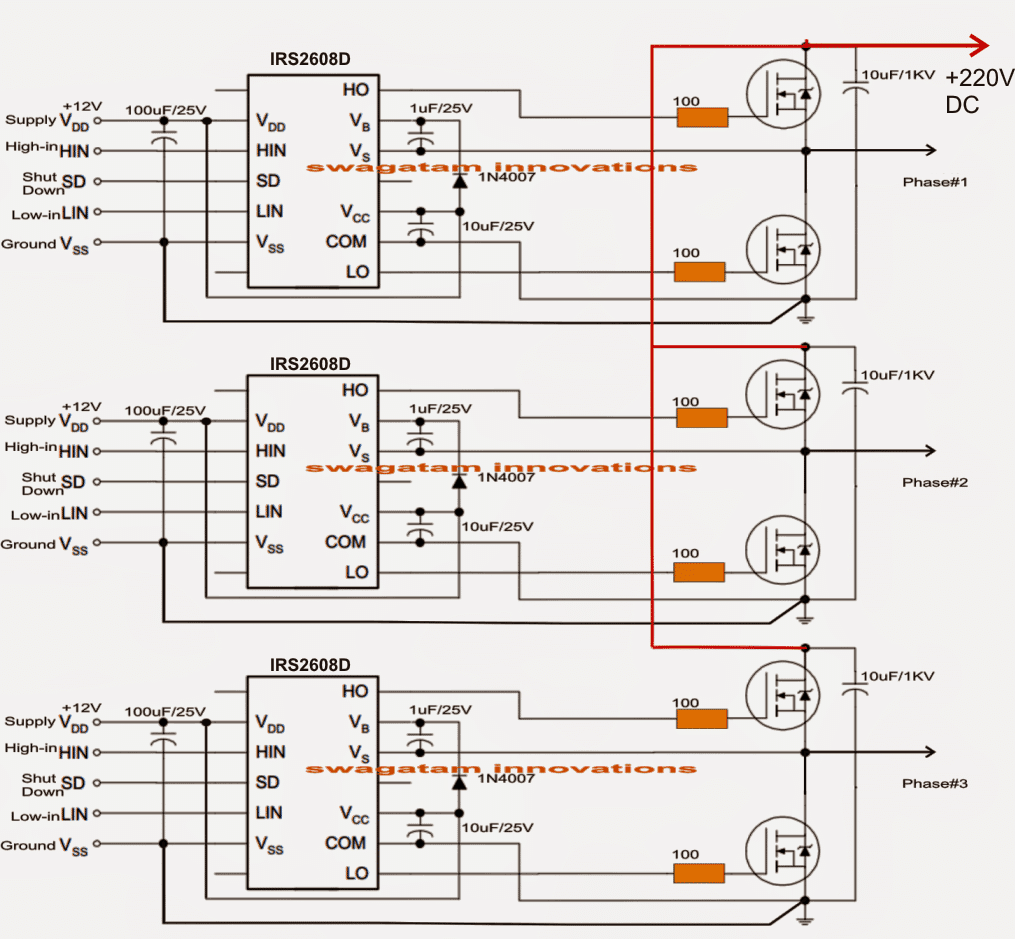
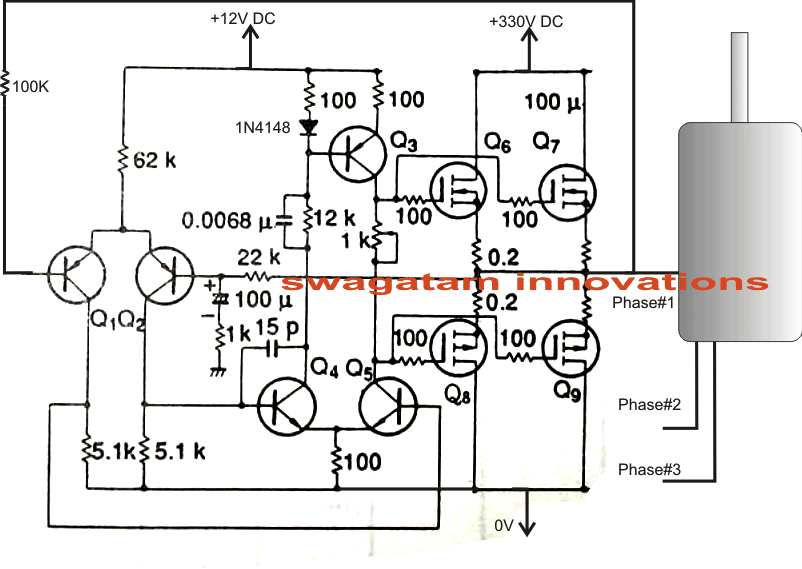
Simple 3 Phase Inverter Circuit - Homemade Circuit Projects

How to Build an Auto-Start Rotary Three Phase Converter ...

Circuit diagram of three-phase inverter with transformer ...

Phase converter - Wikipedia
Wiring Diagram for loads that total up to 1 times the maximum ...
phaseconverter
Phase-A-Matic Rotary Converter Installation Instructions
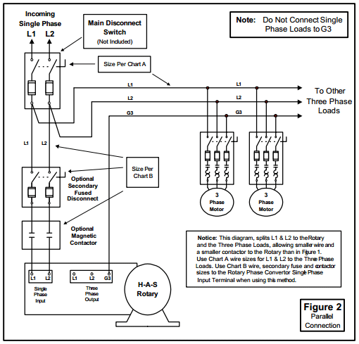
How to Install H-A-S Rotary Phase Conversion System

Graph of phase voltage versus the start capacitor at L1-L3 ...

Three Phase Inverter Circuit Diagram – DIY Electronics Projects

3 - 5 HP HD statischen Phase Converter Mill Bohrmaschine ...
Wiring up a 30HP rotary phase converter | The Hobby-Machinist
Three Phase Inverter Circuit Diagram - 120 Degree and 180 ...
0 Response to "42 3 phase converter wiring diagram"
Post a Comment