38 isolation relay wiring diagram
Wonderful Stove Isolator Switch Wiring Diagram Trailer ... Typical battery isolator circuits arco classic whaler boston reference dual engine how to wire a boat beginners guide with diagrams new marine voltage sensitive relay wiring easy install ezacdc f08d22 auxiliary diagram resources 2019 question the hull truth boating and fishing forum perko inc help guides switch blue water service west michigan ... Isolation Relay Wiring Diagram - justussocializing.org 55 New Battery isolator Relay Wiring Diagram These days, there are several sources that attempt to find the money for Isolation Relay Wiring Diagram to the mechanic online. Most times these providers have either incomplete or incorrect diagrams that can potentially cost the shop wasted time, child maintenance or even possibly a lawsuit.
PDF BI-DIRECTIONAL ISOLATOR RELAY DELAY - Intellitec Check for voltage on coil of isolator relay after engine has been running for at least 20 seconds. Voltage should be approximately 12 Volts. If no voltage, replaceBIRD. If 12 volts is applied to isolator relay coil, check for voltage drop across the isolator relay contacts. If the dropisgreaterthan0.2volts,replacerelay.
Isolation relay wiring diagram
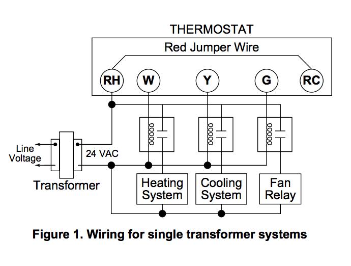
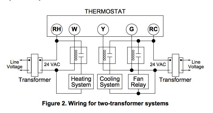
PDF Metering Isolation Relays - Transdata Inc A typical utility customer interface is shown in the FIGURE 1: Wiring Diagram. E. lectrical . The Latching Isolation Relay modules are designed utilizing mercury-wetted relays to provide the required equipment isolation. The K, Y, & Z inputs are connected through LED's, which provide an indication of connectivity ... What is isolation relay? - FindAnyAnswer.com Relays - Thermostats communicate with the heating and cooling equipment via relays. For example, the "W" wire turns on heating, and the "Y" wire turns on cooling. If the wires in the thermostat are correctly and snugly connected, you may have a faulty relay switch. In this regard, how does isolation relay work? PDF Including 3- and 4-Port Isolation Modules with 2- and 3 ... The Lamp Type, Wire Color and Connector Identifi cation charts and diagrams will give specifi c wire colors, their function and locations in connectors. Any special notes are found in the upper right corner of the schematic. Further information and a specifi c troubleshooting guide may be found in the appropriate Mechanic's Guides.
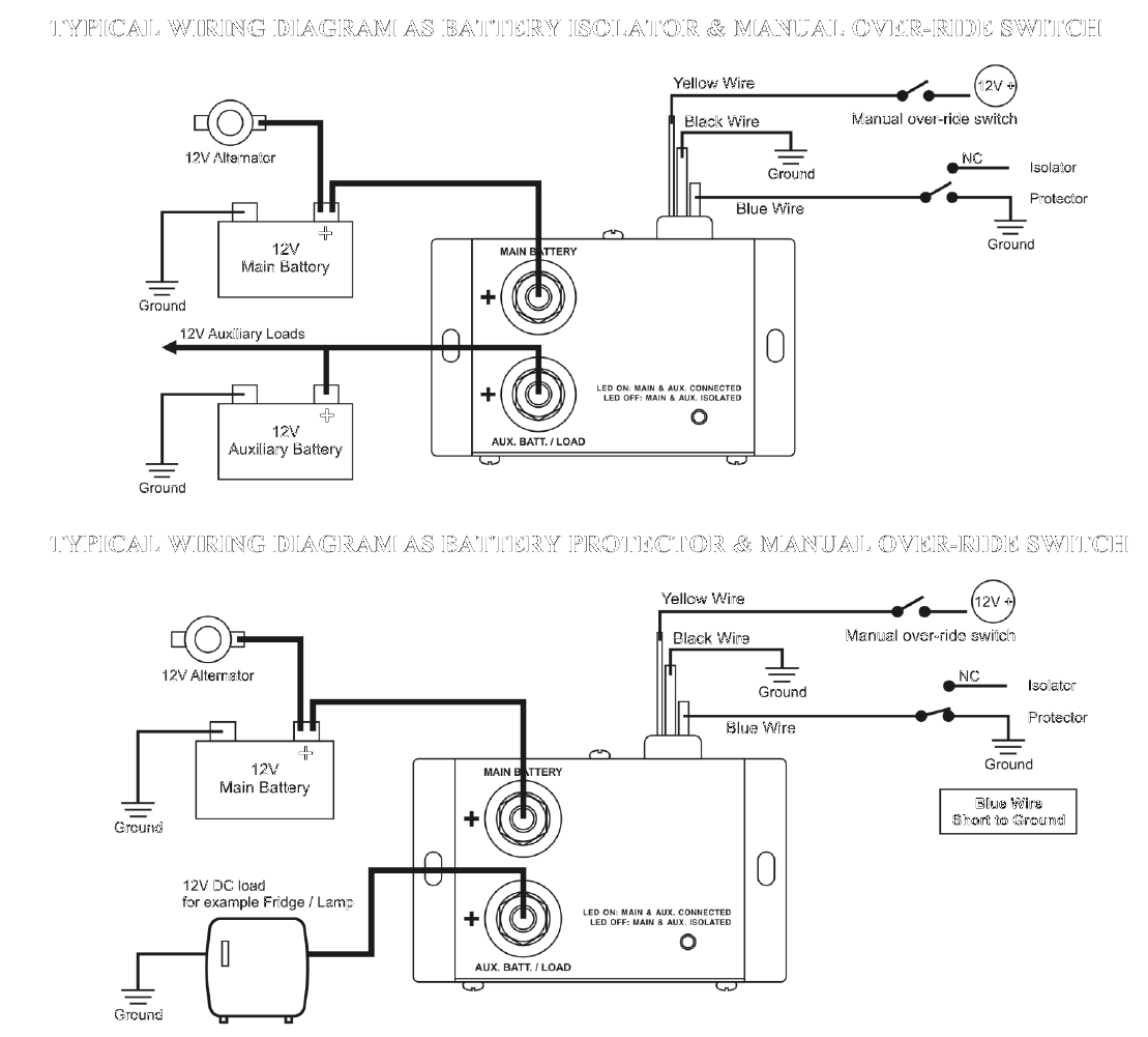
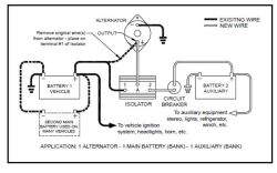
Isolation relay wiring diagram. Stinger Isolator Wiring Diagram - schematron.org terminal of the isolator. (If using the recommended 6 amp circuit breaker [supplied with the C Kit] insert the circuit breaker in the yellow wire as shown in the diagram.) Cut the correct length, strip and crimp on the supplied ring terminal. Now connect the yellow wire to the "E" terminal of the isolator with the lock washer and nut. Honeywell L4064B Combination Fan and Limit ... - InspectAPedia the unit was retrofitted with trane ac in 1998 so the wiring must have been modified at that time. the original diagram had only high speed wired up to a switch, did not have the isolation relay and only had red and white thermostat wires. the isolation relay is a 91-132006-13302 with 24v pair of connections and two 240v switch connections, 240 … PDF Bi-Directional Isolator Relay Delay - Intellitec Typical Installation Diagram The Bi-Directional Isolator Relay Delay constantly senses the voltage on the coach and chassis batteries. If either voltage is above 13.3 volts, which indicates the batteries are being charged, the control closes the isolator relay. Thisparallels thebatteries,charging themboth. PDF Sentry 50 Isolation Relay - Vision Metering The Sentry 50 Isolation Relay provides an electronically isolated interface between the ouput of the utility meter and the electronic measuring equipment such as Data Recorders, Totalizers and Demand Monitoring Equipment. It accepts either a 2-wire Form A or 3-wire Form C open collector or relay contact input and provides three Form A or
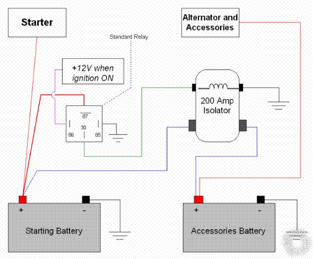
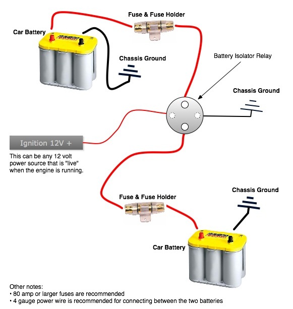
PDF Bi Directional Isolator Relay Delay (B.I.R.D.®) Bi‐Directional Isolator Relay Delay (B.I.R.D.®) Part number: 00‐01136‐000 The B.I.R.D.® was designed to make installation simple. With its all in one integrated design, Intellitec brought the electronics to the source, eliminating additional wiring and simplifying the installation process. Isolation relay for the oil or gas furnace, diagram - YouTube This one shows how to wire the isolation relay sometimes used with oil furnaces. This video is part of the heating and cooling series of training videos mad... PDF UTILITY SWITCHING DEVICE - BEA Americas 24VAC DPDT ISOLATION RELAY COIL INPUT 24VAC +/- 5% CONTACT RATING 10A @ 24 VDC / 120VAC DIMENSIONS - Relay - Socket 1 3/8" x 1" x 7/8" 2 5/8" x 1 3/8" x 1" The 10REL24V / 10REL24VDC Isolation Relay is used as a utility Switching device. It can be used for the following applications as well as any general-purpose voltage isolation. PDF Smart Battery Isolator Installation Instructions Wiring Diagram Wiring the relay: 1. The black wire coiled inside the relay needs terminated to a good ground location using the included blue crimp connector. This wire is simply used as a ground for activating the relay. 2. One terminal on the relay should be connected to the positive terminal of the primary starting battery using 6ga red wire.
PDF Metering Isolation Relays - Transdata Inc A typical utility custom er interface is shown in the FIGURE 1: Wiring Diagram. Electrical The Latching Isolation Relay modules are designed u tilizing mercury-wetted relays to provide the required equipment isolation. The K, Y, & Z inputs are conn ected through LED's, which provide an indication of conne ctivity and proper circuit operation. What are Isolation relays? - Quora Answer: In isolated mode the relay is completely electrically isolated from the control side. Large voltage spikes, shorts, etc. will not affect your controller. Therefore you need two separate voltage sources. One is for the relay side. This is put in the terminals closest to the edge. Use the t... Looking Good Ats Wiring Diagram For Standby Generator Ge ... A wiring diagram is a simplified standard photographic representation of an electrical circuit. Generator changeover switch wiring diagram best generac transfer. Technical information 3 standard diagrams transfer between 2 sources 1 bus bar comut 041 a load g s1 g s2 p1 p2 standard solution comut 042 a load s1 s2 q1 q2 ats socomec solution ... How To Install A Battery Isolator In Your Conversion Van ... This is the most complicated of the options to install because you have to wire in a signal to the relay. 12 volt rocker switch. For battery isolation, you want your relay to activate when the van is running. The best way to do this is to find the "accessory" wire in your fuse box and tap into that wire.
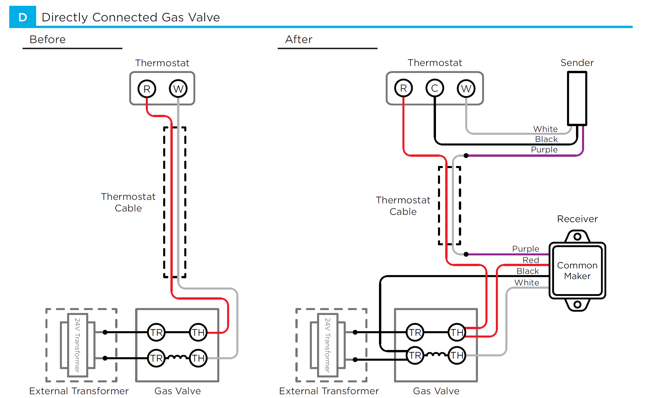
My thermostat has only two wires. Am I compatible with ecobee?
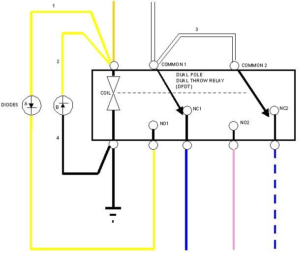
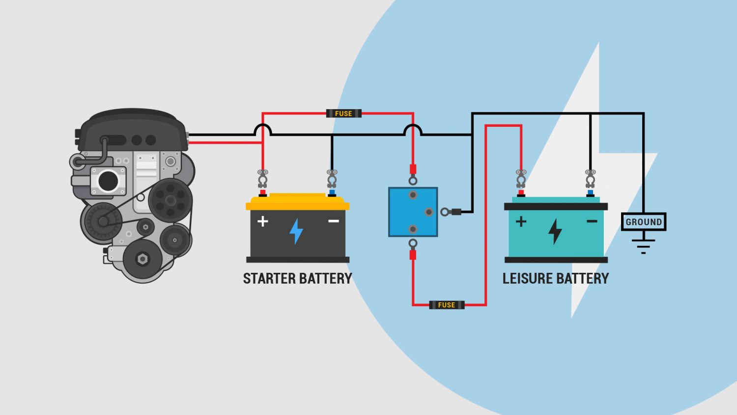
Dual Battery Isolator Schematic (simplified) Diagram The diagrams below are intended as an overview and some details are missing from them. The Diode Battery Isolator The diode type battery isolator uses semiconductor diodes to split the current from the alternator or generator and charge 2 or more batteries at the same time.
Honeywell L4064B Combination Fan and Limit Control: How to ...
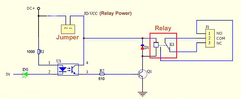
RelayIsolation - ArduinoInfo - MyWikis For complete optical isolation, connect "Vcc" to Arduino +5 volts but do NOT connect Arduino Ground. Connect your Arduino Digital Output pins to "IN0", "IN1" etc. Connect a separate +5 supply to "JD-Vcc" and board Gnd. This will supply power to the transistor drivers and relay coils. Look at the diagram above.
Battery Isolator Wiring
PDF ISOLATOR RELAY DELAY/E - Intellitec If 12 volts is applied to isolator relay coil, check for voltage drop across the isolator relay contacts. If the drop is greater than 0.3 volts, replacerelay. Check voltage on module with ignition off. (Red and Blue wire) should be 0 volts. If not, check wiring. Check for continuity across the isolator relay contacts, the relay should be open ...

Wiring a Opto-Isolated Relay to Arduino - General Electronics ...
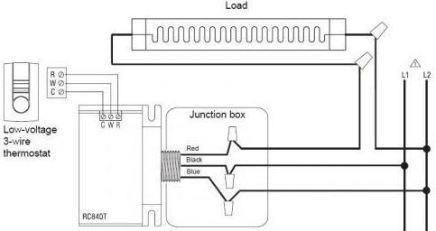
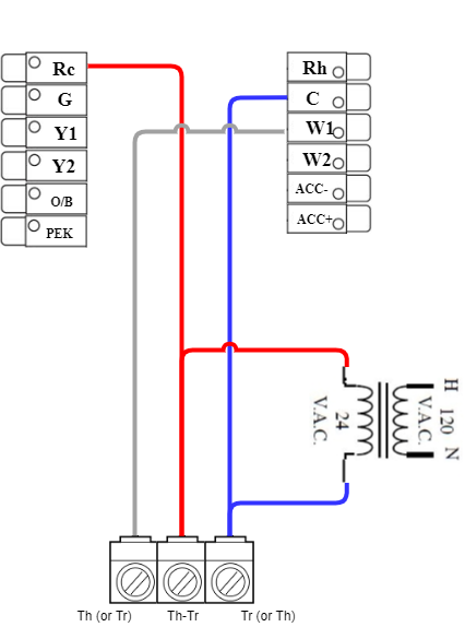
How to wire isolation relay to create C-wire - Home ... Highest score (default) Date modified (newest first) Date created (oldest first) This answer is useful. 2. This answer is not useful. Show activity on this post. You actually happen to have the relay oriented in your photo the same way the relay in the diagram is oriented. W1 to terminal 1. C to terminal 3.

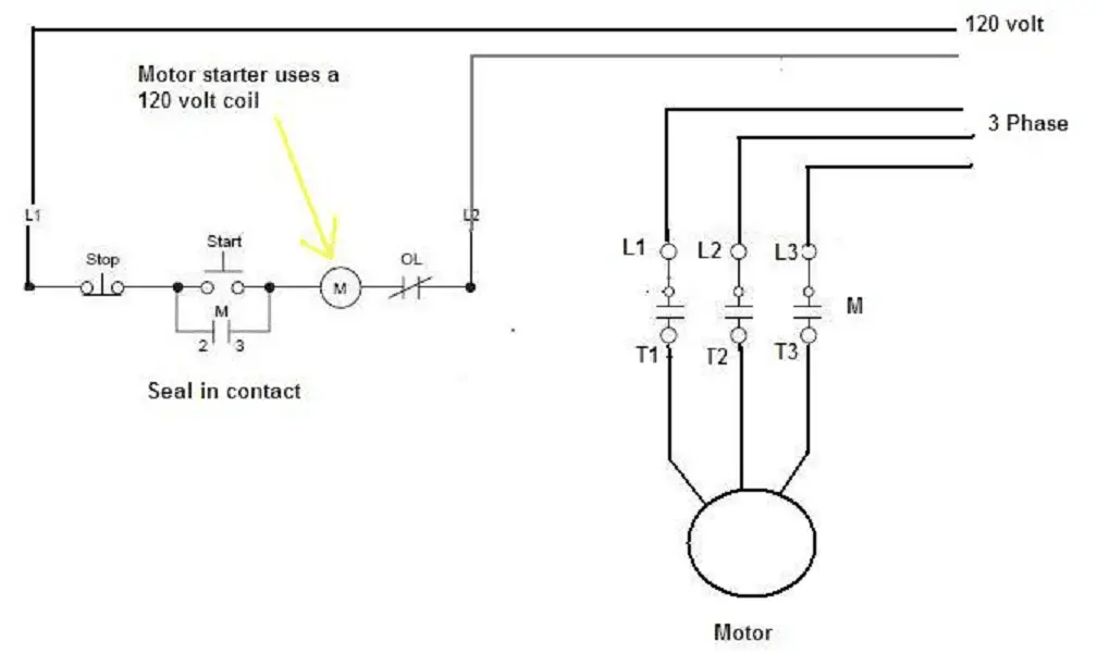
How to wire contactor, Overload Relay with Motor/ Power and ...
PDF Including 3- and 4-Port Isolation Modules with 2- and 3 ... The Lamp Type, Wire Color and Connector Identifi cation charts and diagrams will give specifi c wire colors, their function and locations in connectors. Any special notes are found in the upper right corner of the schematic. Further information and a specifi c troubleshooting guide may be found in the appropriate Mechanic's Guides.

Isolation relay for the oil or gas furnace, diagram
What is isolation relay? - FindAnyAnswer.com Relays - Thermostats communicate with the heating and cooling equipment via relays. For example, the "W" wire turns on heating, and the "Y" wire turns on cooling. If the wires in the thermostat are correctly and snugly connected, you may have a faulty relay switch. In this regard, how does isolation relay work?
Intrinsic Relay Wiring Diagram | Gems Sensors
PDF Metering Isolation Relays - Transdata Inc A typical utility customer interface is shown in the FIGURE 1: Wiring Diagram. E. lectrical . The Latching Isolation Relay modules are designed utilizing mercury-wetted relays to provide the required equipment isolation. The K, Y, & Z inputs are connected through LED's, which provide an indication of connectivity ...
12 volt and 24 volt 80 amp DC battery isolator and split ...
VW CRAFTER 2013 – Preparation for tail lift . Wiring diagrams ...

Roadtrek Modifications/ Mods, Upgrades, and Gadgets.: DIY ...
200 Amp Relay and Automotive Battery Isolator | Oznium
84-86 isolaiton relay - Pennock's Fiero Forum
What Charges the House & Chassis Batteries When - Page 3 ...
Nest Thermostat isolation relay? - DoItYourself.com Community ...

Opto-Isolated Relay Switching Module. Arduino and Raspberry ...
Honeywell L4064B Combination Fan and Limit Control: How to ...

Battery Management Wiring Schematics for Typical Applications ...

Honeywell R8285E Control Center Installation Guide - Manuals+
e102 Message on baseboard heating system (boiler)

90-360 - White Rodgers 90-360 - Fan Relay, Type 184, 24 VAC ...
Blue Sea ML-ACR 500 AMP Dual Battery with remote wiring and ...
16 Series
Cyan Infinite - Controlling devices with the Opto-isolator Relay

How can I safely wire Nest to this transformer? — Heating ...

Interposing Relay Application, Advantages, Function ...
Campervan Split Charging: A Helpful Illustrated Guide ...
Wiring diagram for Battery Isolator | etrailer.com
My thermostat has only two wires. Am I compatible with ecobee?
How Relays Work | Relay diagrams, relay definitions and relay ...
200 Amp Relay and Automotive Battery Isolator | Oznium
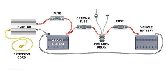
How to Turn Your Truck Into a Generator (DIY) | Family Handyman
Wiring Argo IR882 Isolation Relay
Odd Thermostat "Fan On" issue | DIY Home Improvement Forum

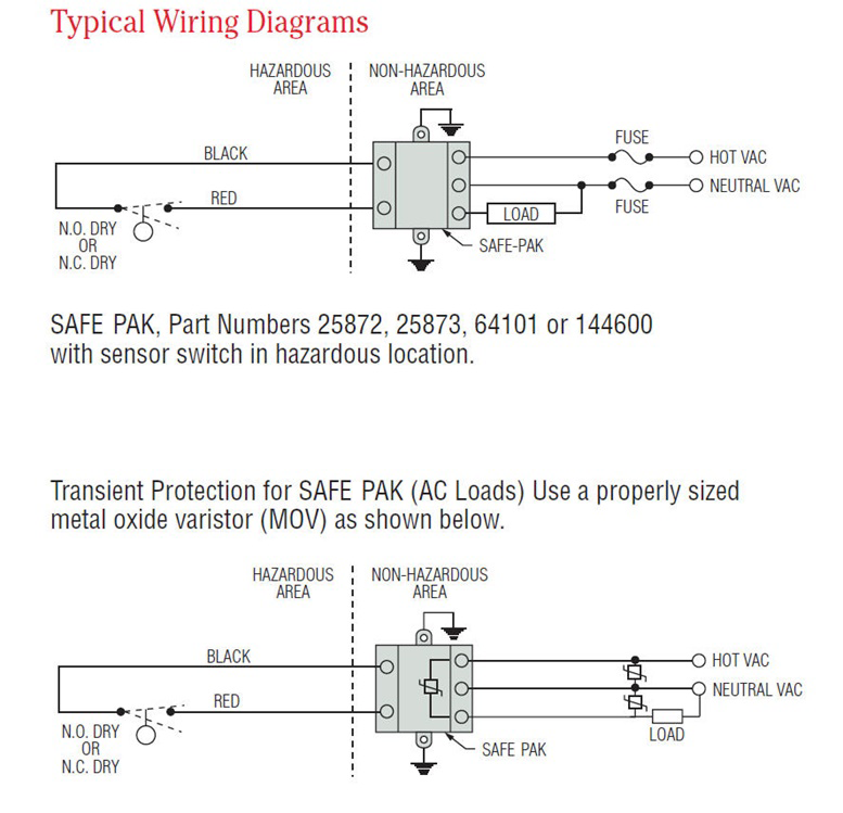
Safety Circuit Examples of Safety Components | Technical ...
Wiring Interposing Relays - NPN PNP Isolation | Acc Automation
Successful installations without connecting the C wire. - Page 2

Control Relay 】 What is a Control Relay?
How do i wire the ASCO 108D90C and 173A19? | ASCO Power ...
0 Response to "38 isolation relay wiring diagram"
Post a Comment