40 water pump installation diagram
Installed near the tank inlet to hold water in the tank during pump installation when the pump is idle. 8. Tank Tee Connets water line from pump to pressure tank and service line from tank to house. Taps are provided to accept Pressure Switch, Pressure Gauge, Drain Valve, Relief Valve, Sniffer Valve, etc. 9. Drain Valve Drain easy draining of ... This DIY guide to installing a campervan water system will show you how to install an RV hand sink pump, foot sink pump and 12V electric sink pump. Learn how to set up your water tank, run plumbing and collect waste water. Simple, easy to read instructions on 12 volt systems and example RV installation.
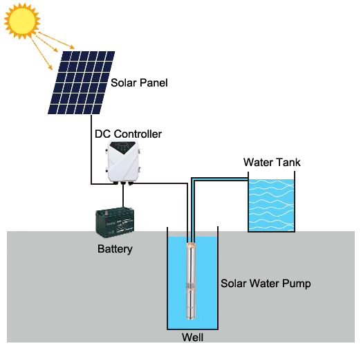
Pump Controller rope Water pipe Pump down lead WH sensor (Prevents the pump from running dry) WC sensor (common) TC sensor (common) TH sensor (full tank) Circuit with pump controller, sensors and solar PV panel array Diagram shows how to connect an optional solar charge controller and deep cycle battery.

Water pump installation diagram
1 1/4" holes are full of water. STEP 5 Mount the pump onto the well adapter with gaskets and bolts, making sure that the 1 1/4" and 1" holes in pump line up with the holes in th e adapter. STEP 6 Prime the pump by pouring water into the discharge of the pump housing or automatic regulator mounted in discharge of the pump on some models. Mount the valve under the sink and the pump at the water heater. The valve's unique thermal disk technology sends cooled water back to the water heater so hot water lines remain hot. Cleaning made easy. There's no need to remove the Hot-Link valve from the piping to keep it clean. Our exclusive clean-in-place design makes short Install a one-way check valve in the feed line that goes to the pump. This will keep water in the shallow well pump and the plumbing system instead of going back down into the well. Run the shallow well pump and check several water samples before you use them. The water should be clean and free of silt, sand or other materials before you use it.
Water pump installation diagram. replace an existing submersible water-well pump or pump motor. This manual should be retained for future reference. • INSPECT THE NEW PUMP: Occasionally, ... The water pump used in the hot water recirculating pump is ideally of a softball size. It is generally installed above the water heater or just below the sink. In most of the cases, installation above the heater has been rated to be one of the excellent options. Aug 25, 2015 - Basic installation layout for water pressure booster pumps ... above ground storage tank diagram Well Water System, Water Pump System, ... Installation). Step 2 Connect the pump to the water circuit. Step 3 Connect the power to the pump. To ensure normal running of your water system, follow the checklist below: • Remove air from the circuit (to prevent priming issues, drop of performance, noise and vibration). • Check the priming of the pump (the strainer should be filled with ...
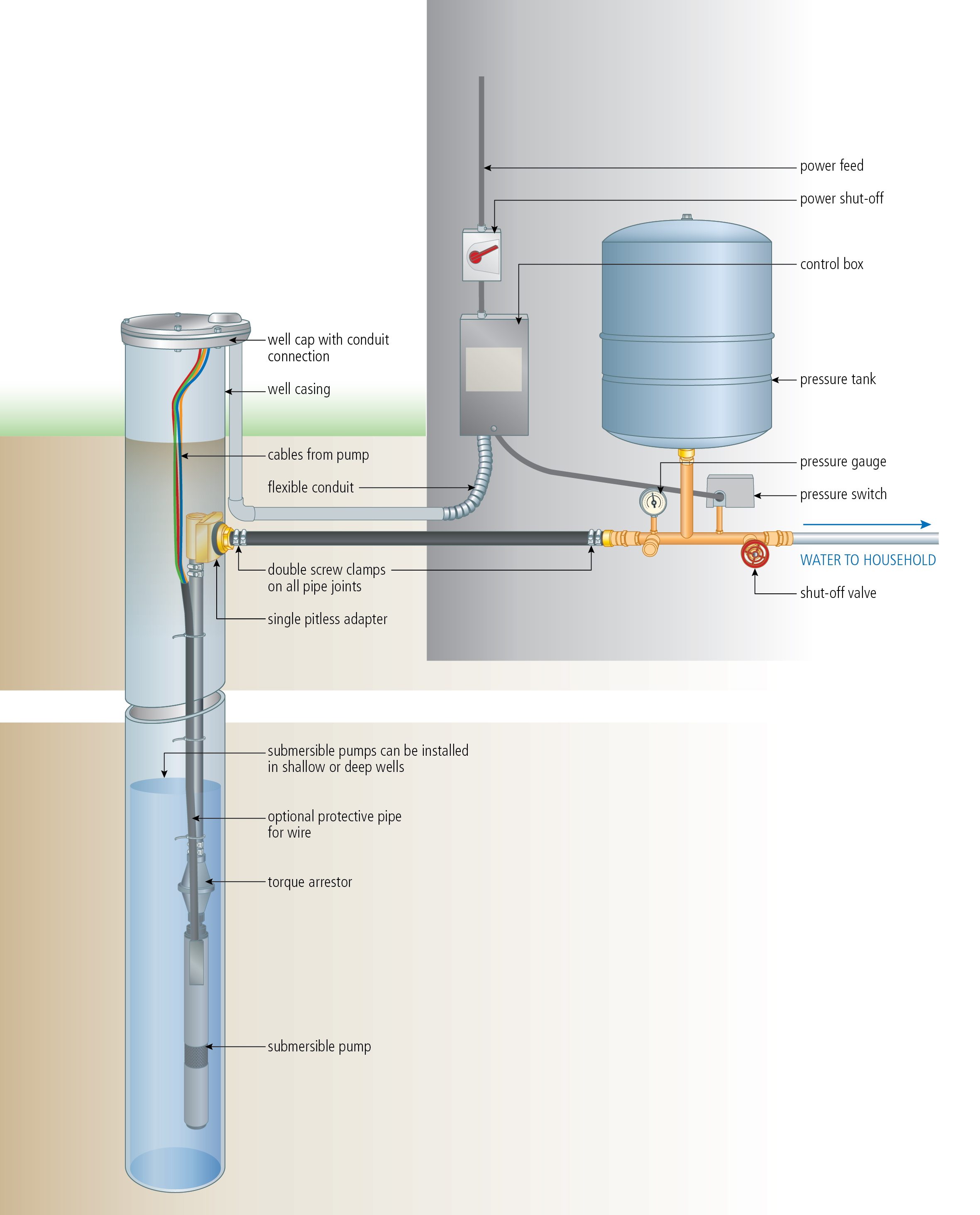
The booster pump is controlled by a single control. When the flow switch senses that water is flowing it starts the booster pump. When the water stops moving in the pipe the flow switch automatically shuts down the booster pump. INSTALLATION The following guidelines should be met at installation. 1. Install the booster pump system on firm level ... Prevents surface water from seeping around casing into potable water. 11. Threaded and coupled galvanized pipe should be used on extremely deep wells. Threaded schedule 80 PVC and a heavy grade poly pipe are also available and are much lighter and easier to work with. 12. Position a torque arrestor directly above the top of the pump. Diagrams --Typical Pump Installations. The information provided here is for educational purposes only. Technically qualified personnel should install pumps and motors. We recommend that a licensed contractor install all new systems and replace existing pumps and motors. Failure to install in compliance with local and national codes and ... Well Diagram. The quality water system products described here and illustrated on the front page are some of the Baker Water Systems products used in a typical well system. (The section in the catalog where these items can be found is located in parentheses) This list and the illustration on the front page are not intended as an installation guide.
Permeate Pump decreases the time to fill the tank, but it does not reduce the amount of water produced. For manifold type RO systems, contact the factory for installation recommendations. Technical Specifications Part number: ERP 1000 Pump Type: Positive displacement, reciprocating, single action diaphragm, hydraulically driven Weight: 1 lb. Water Pump - The Heart of the Plumbing System. The water pump pressurizes the water lines, much like a heart to the circulatory system. It is located just outside of the fresh water tank, where it pulls the water through itself and into the water main. The 12-volt water pump should be turned off when you aren't going to be near the RV. Home > Technical Information > Pumps Technical Data > Submersible Well Pump Technical Data > Submersible Well Pump Accessories Installation Diagram This illustration is for educational purposes It is not intended as an installation guide. Grundfos Home Water Booster Pump.⭐ Compare Our Price & Models Today!✓Grundfos Has Good Reviews & Best Reliability Quality. Low or shifting water pressure is ...
Simple Water Tank Diagram Download Scientific Diagram
Schematic Diagram Of Pv Water Pumping System Scientific. Control Two Submersible Pumps Alternately Homemade Circuit Projects. Control Panel For Submersible Molock Pumpset Pump Starter Circuit. 3 Phase Solar Submersible Pump Inverter Circuit Homemade Projects. Automatic Water Pump Controller Full Circuit Available.

How A Well Pressure Tank Works With Diagrams Plumbing Sniper
We're doing the plumbing on a new house and well, the water pump installation works which makes me very happy. It's good for heights up to 36M and my roof is...
Water Pump Diagram Images Stock Photos Vectors Shutterstock
Product Information Pump water with ease with the submersible solar energy pump that fits in many wells and water systems without displacing much water. The pump weighs 3 kilograms and allows for fast and easy installation. The device is made of a stainless-steel fastener and inlet that makes it non-corrosive and long-lasting.

Water Pump Wiring Diagram Water Motor Wiring Water Motor Wire Connection Single Phase Motor Youtube
Electric Water Pump Installation Guide (Continued) Page 2 FORD SB(260-351W, 351C-400M, BB 429-460 ONLY: Using the gasket, 5/16" fasteners, and cover plate provided, apply sealant to the gasket and hand-tighten in place with the additional fasteners provided. The last four (4) fasteners will be used to secure the water pump to
1100w 110v Dc Solar Water Pump Inverter Com
Before Installation. Well pump installation can be dangerous when dealing with water and electricity, so extreme caution must be taken. Before getting started, look up your owner's manual and read over the precautions and all other warnings before beginning the installation. The manual will contain important safety precautions, wiring diagrams, tools required for assembly, proper grounding ...
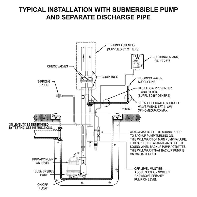
How To Install A Water Powered Emergency Backup Sump Pump
The Typical Pump Installation Set Up is evident in the nearby photo. The Suction Valve, Discharge Valve, Strainer, and Check Valve are labelled. All PTOA Readers and Students who stick with the PTOA will soon be able to identify the hardware components found in the Typical Pump Installation Set Up without any labels ...

Water Pump Installation Works Youtube
The Ideal Supply Tank Installation. Page 13. The Ideal Pump Chamber Installation. Page 14. Using a Pressure Vessel. Pages 15-16 The Installation Procedure.

Pump Kit Polyworld
TYPICAL DEEP WELL JET PUMP INSTALLATION a captive air Jet pumps usually come with a 30-50 pressure switch factory installed on the pump. If replacing the switch we recommend using one with a 30-5 psi setting. 1. Deep well jet systems are used when the water depth is between 20' and 80'. For wells deeper than 80' a submersible pump system ...
House
25mm Plumbing kit with Pump and Cover Do not directly install water pumps to the side of your water tank. The water pump and its motor must be self-supported on its own mount and connected to the tank via flexible hose to isolate any vibration or movement by the pumping unit itself.

Wavly Auto Cut Manual On Automatic Off Controller Preventing Overflow Of Water Tank Better Than Water Alarm Bell Siren Home Automation Security System With Free Sensors Amazon In Home Improvement
Booster Pump Installation Instructions 1. Install pressure switch in tank line. (See diagram on back for where to place the pressure switch). 2. Pump must be located within 2 feet of pressure switch and within 6 feet of power outlet. A. Pump can be mounted to the wall horizontally in either direction or vertically only one way ~ with pump head and

Amisjet Robojet Automatic Air Feeders For Water Booster
Here is a visual representation of how the installation process seems. Submersible Water Pump Installation Diagram. submersible-water-pump- ...

Lefoo Lfpc 1 Automatic Water Pump Controller For Water Pump Manual Set Zhejiang Lefoo Controls Co Ltd Pdf Catalogs Technical Documentation Brochure
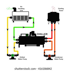
Water to Water Geothermal Heat Pump Installation & Operating Instructions Model: THA/THT-*** ... THT 3-Phase Electrical Diagram 57 Warranty Information - GX002 58 . 12/03/2012 1 GI101 Introduction ... Ground Water Heat Pump Ground Loop Heat Pump .
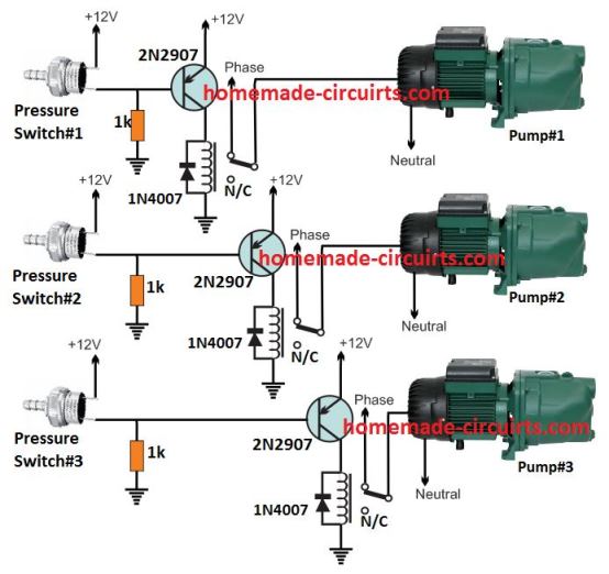
Pressure Switch Water Pump Controller Circuit Homemade Circuit Projects
Pump H C H Water Heater Cold Water Inlet Hot Cold • A built-in temperature sensor automatically turns the pump on when the water temperature in the hot water supply line cools down to 85 ºF (29 C) (for ACT-303-BTRW model, refer to instructions on page 5). The pump then moves the cool water in the hot water supply line into the cold water ...
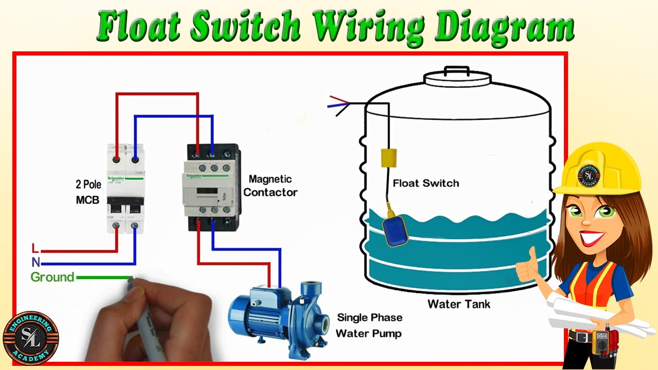
Float Switch Wiring Diagram For Water Pump How To Make Automatic On Off Switch For Water Pump Youtube
Once you're in the 'Catalogue' section, select either 'Pump designs', 'Applications' or 'Product families', depending on what you need. Select your product. Step 3: Download manuals. After you've selected your product, go to the 'Documents' tab to find 'Installation & Operating Instruction'.

Schematic Diagram Of The Proposed Water Pumping System Download Scientific Diagram
your local electrical and pump professionals. 2. Install tank as close as possible to the pump pressure switch to reduce friction loss and elevation difference between the tank, water supply main, and switch. 3. After installation, be sure the pressure switch is set low enough to shut the pump off. If all valves are closed and the pressure switch
1
Keywards:toilet repairplumbing servicesemergency plumberdrain cleanerlocal plumberswater heater installationplumbing companiesplumbers near meclogged drainbl...

Schematic Diagram Of Solar Water Pumping System Download Scientific Diagram
Install a one-way check valve in the feed line that goes to the pump. This will keep water in the shallow well pump and the plumbing system instead of going back down into the well. Run the shallow well pump and check several water samples before you use them. The water should be clean and free of silt, sand or other materials before you use it.
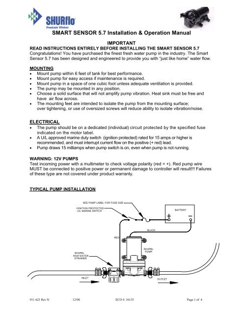
Smart Sensor 5 7 Installation Amp Operation Manual Shurflo
Mount the valve under the sink and the pump at the water heater. The valve's unique thermal disk technology sends cooled water back to the water heater so hot water lines remain hot. Cleaning made easy. There's no need to remove the Hot-Link valve from the piping to keep it clean. Our exclusive clean-in-place design makes short

System Diagram Of Water Source Heat Pump Water Heater Wshpwh System Download Scientific Diagram
1 1/4" holes are full of water. STEP 5 Mount the pump onto the well adapter with gaskets and bolts, making sure that the 1 1/4" and 1" holes in pump line up with the holes in th e adapter. STEP 6 Prime the pump by pouring water into the discharge of the pump housing or automatic regulator mounted in discharge of the pump on some models.
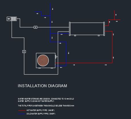
Heat Pump Geyser Installation Diagram Cad Files Dwg Files Plans And Details
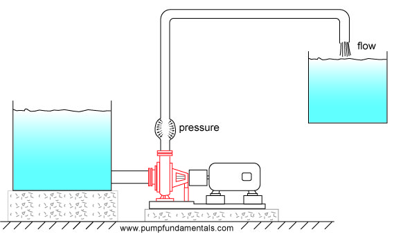
How To Design A Pump System

How To Wire A Microswitch Tap And Water Pump Off Grid Camper

Installation And Operating Manual Dab Pumps Water Pages 1 15 Flip Pdf Download Fliphtml5
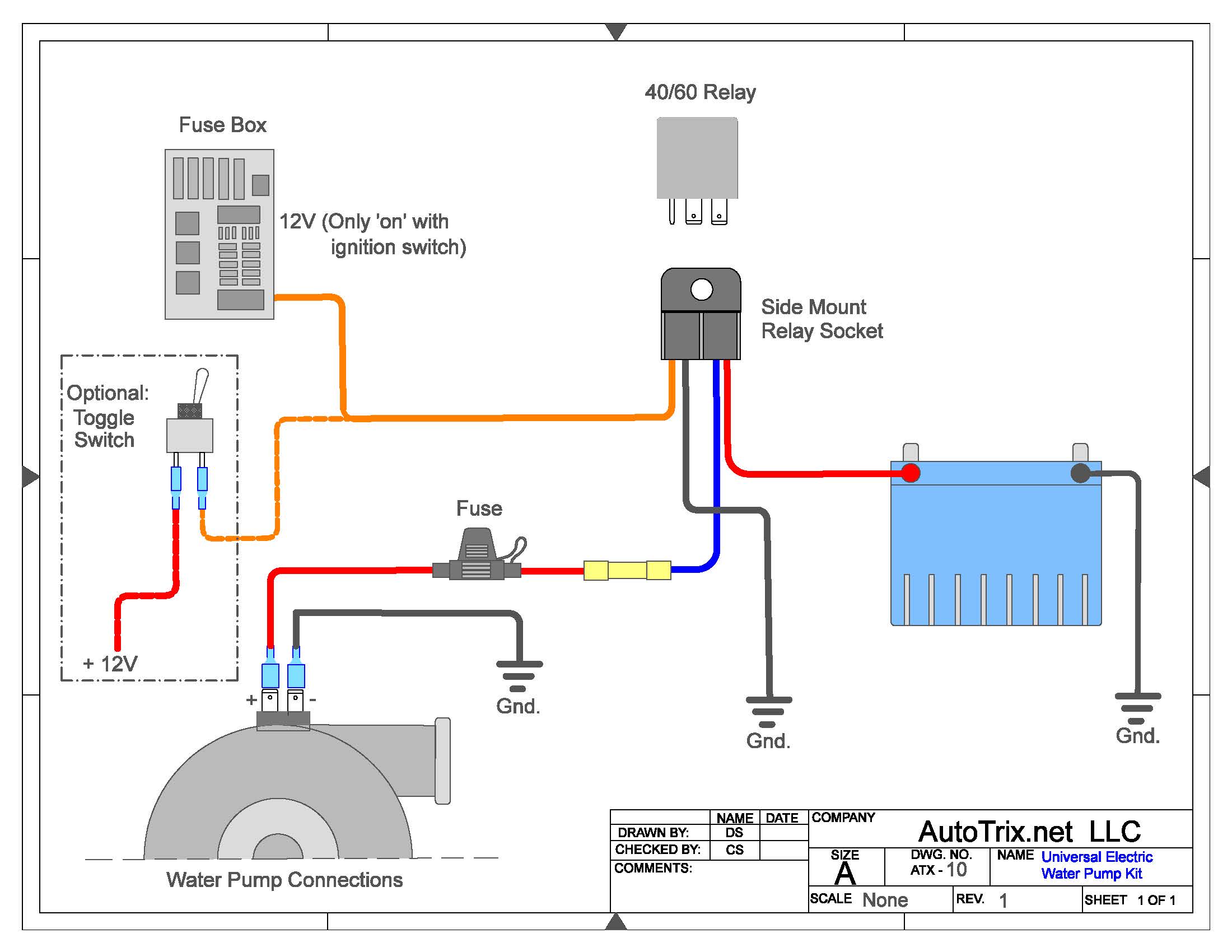
Universal Electric Water Pump Relay Kit Autotrix Net

Tech Information Csr
How To Install Water Pump Water Pump Installation Pumpkart Com

Grundfos Sqflex Solar Water Pump Wiring Diagram
Diy Fittings For Installing Tsunami Domestic Water Pump Shopee Malaysia
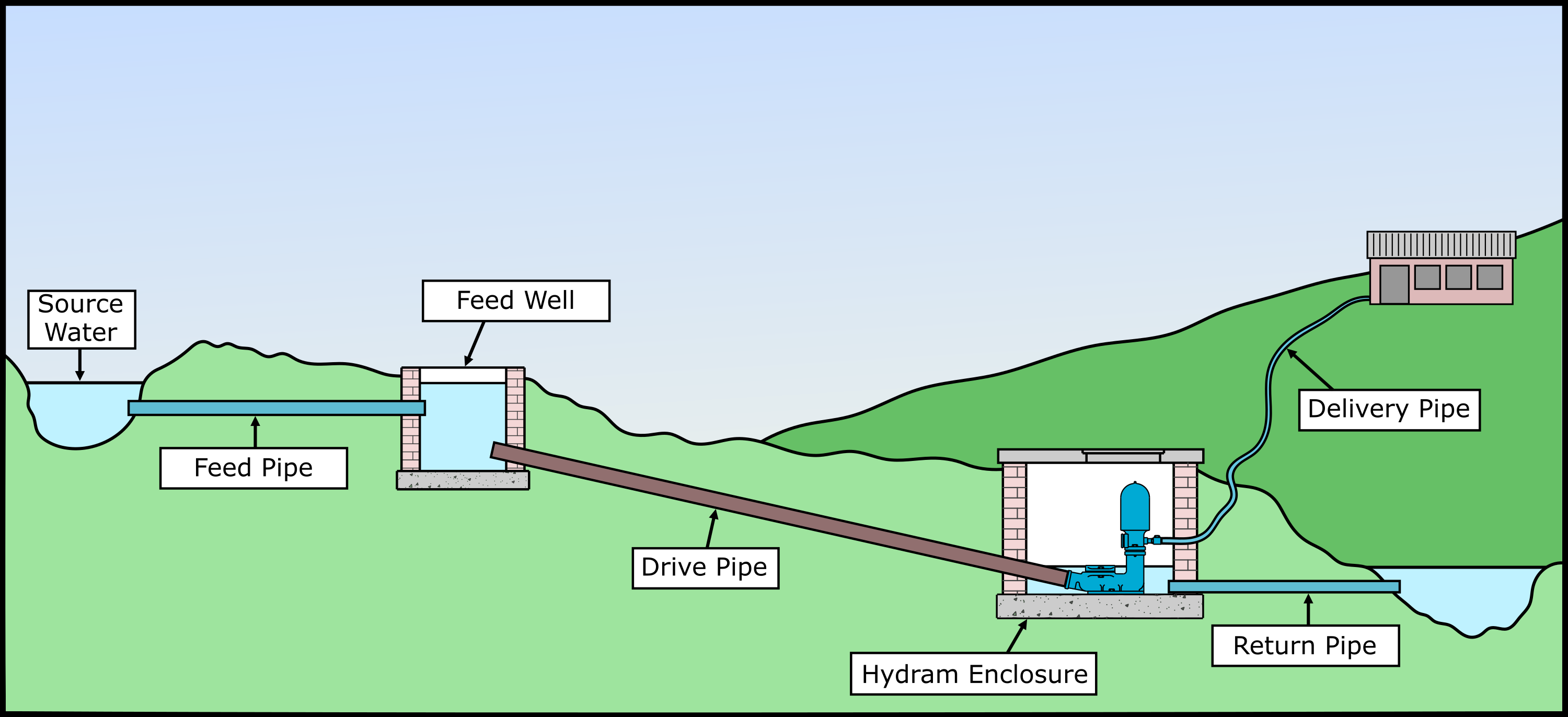
Installation Blake S Hydram Water Pump Installation

3 Dc Solar Submersible Well Water Pump 6pcs Mono Solar Panel Mppt Controller Pumps Aliexpress

Schematic Diagram Of A Solar Water Pump Optional Components Are Shown Download Scientific Diagram
Install A Submersible Pump 6 Lessons For Doing It Right

Float Switch Wiring Diagram For Water Pump Youtube

Installation Of A Low Tower Electric Water Pump Download Scientific Diagram
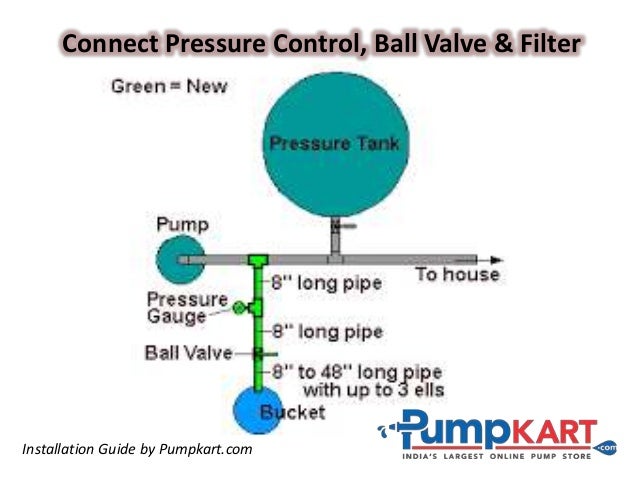
How To Install Water Pump Water Pump Installation Pumpkart Com

Schematic Diagram Of Pv Water Pumping System Download Scientific Diagram
Torrium Com

Install Whole House Pumps How To Pages
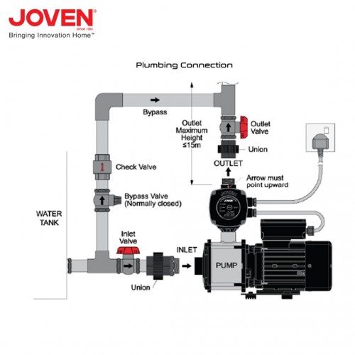
Joven Jhp 2 30 Jhp Series Automatic Domestic Water Pump 0 37kw 0 50hp

Deep Well Pump Installation Instructions In 2021 Deep Well Pump Well Pump Shallow Well Jet Pump
0 Response to "40 water pump installation diagram"
Post a Comment