36 draw the free-body diagram for the rod. g is the center of gravity of the rod.
In case of solid sphere, both CG and center of mass lie at center of the sphere. For a body of very large dimensions and having non-uniform density, the center of gravity does not coincide with the center of mass. Calculation of Center of Gravity. Calculate the center of gravity of following diagram: Step 1: Draw Free Body Diagram of the System
• Draw Free Body Diagram for all forces ... Concept Question: Tension and String Theory A ball is suspended from a vertical rod by two strings of equal strength and equal length. The strings are very light and do not stretch. The rod is spun with a ... the center of mass of the bucket and the
Problem 5-6 Draw the free-body diagram of the smooth rod of mass M which rests inside the glass. Explain the significance of each force on the diagram. Given: M = 20 gm a = 75 mm b = 200 mm θ = 40 deg Solution: A x , A y , NB force of glass on rod. M(g) N force of gravity on rod.
Draw the free-body diagram for the rod. g is the center of gravity of the rod.
Draw the free-body diagram of the uniform . beam. The beam has a mass of 100kg. 5-8 Free-Body Diagrams. ... The train car has a weight of 120 kN and a center of gravity at G. It is suspended from its front and rear on the track by ... The jib crane is supported by a pin at C and rod AB. If the load has a mass of 2
Need more help! Draw the free-body diagram of the crane boom AB which has a weight of 650 lb and center of gravity at G. The boom is supported by a pin at A and cable BC. The load of 1250 lb is suspended from a cable attached at B. Explain the significance of each force acting on the diagram. (SeeFig)
diagram for one object, there is an opposite force vector that appears in the free-body diagram for another object. An example involving two blocks on a table is shown in Fig. 4.1. If a person applies a force F to the left block, then the two free-body diagrams are shown (assume there is no friction from the table).
Draw the free-body diagram for the rod. g is the center of gravity of the rod..
the pivot. Be sure to include a free body diagram. Concept Question: The natural frequency of the pendulum without a torsional spring is independent of mass and equal to n g L Z How will the natural frequency change as a result of the addition . Independent of the mass of the spool. for µ= 0.2 φ= 30o L = 0.25m g = 9.81m s2 Ω= 5.87radians sec 7
As usual, we should begin with a diagram of the situation. A free-body diagram is also very helpful. These are shown in Figure 9.7. (a) On the block's free-body diagram, we draw a downward force of gravity, applied by the Earth. We also draw an upward force of tension (applied by the string), and, because the block displaces some fluid, an upward
2. The object in the diagram below is on a fixed frictionless axle. It has a moment of inertia of I = 50 kgm2. The forces acting on the object are F1 = 100 N, F2 = 200 N, and F3 = 250 N acting at different radii R1 = 60 cm, R2 = 42 cm, and R3 = 28 cm. Find the angular acceleration of the object.
Draw the free-body diagram of the dumpster D of the truck, which has a weight of 5000 lb and a center of gravity at G. It is supported by a pin at A and a pin-connected hydraulic cylinder BC (short link). Explain the significance of each force on the diagram. (SeeFig)
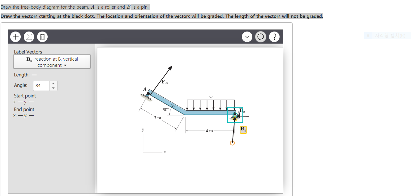
Draw the free-body diagram for the rod. G is the center of gravity of the rod. Draw the vectors starting at the black dots. The location and orientation of the vectors will be graded. The length of the vectors will not be graded. Part C. Draw the free-body diagram for the rod. B is a roller and A is a pin connected to collar on smooth rod.
To set up the equilibrium conditions, we draw a free-body diagram and choose the pivot point at the upper hinge, as shown in panel (b) of (Figure). Finally, we solve the equations for the unknown force components and find the forces. Figure 12.17 (a) Geometry and (b) free-body diagram for the door.
draw the free body diagram for the rod. B is a roller and A is a pin connected to collar on smooth rod. G is the centre of gravity of the rod.
wheelbarrow to the center of gravity of the second bag if she can hold only 75 N with each arm. PROBLEM 4.2 A gardener uses a 60-N wheelbarrow to transport . ... Free-Body Diagram: For no motion, reaction at . A must be downward or zero; smallest distance a for no motion corresponds to
Draw free-body diagrams that conform to the assumed displacement positions and their resultant reaction forces (i.e., tension or compression). c. Apply to the free body diagrams to obtain the governing equations of motion. The matrix statement of Eqs.(3.123) is The mass matrix is diagonal, and the stiffness matrix is symmetric.
• a) Draw a free-body diagram for each block. • b) Determine the acceleration of the system. ... We will drwas two free body diagrams for this problem, and the reason is that ... 4.00 kg in the gure above is attached to a vertical rod by two strings of length = 2.00 m. The strings are attached to the rod at points a
Assume the rod is weightless, rigid and amply strong and the rope is flexible and amply strong. Step 1: Draw Free Body Diagram (FBD) of the rod The tension force in the rope will be of same magnitude on both sides of the pulley, otherwise the pulley will roll. Thus, the force exerted by the rope on the rod will also be 50# acting at 60o angle.
Examples of drawing free-body diagrams. To better understand how to draw free-body diagrams using the 3 steps, let's go through several examples. Example 1. A box is pushed up an incline with friction which makes an angle of 20 ° with the horizontal. Let's draw the free-body diagram of the box. The first step is to sketch what is happening:
Draw the free-body diagram for the rod. B is a roller and A is a pin connected to collar on smooth rod. G is the center of gravity of the rod. Draw the vectors starting at the black dots. The location and orientation of the vectors will be graded. The length of the vectors will not be graded. Please show all work.
Part A The uniform rod has the center of mass at G and it is pinned at end A. Draw the free-body diagram for the rod. Draw the vectors starting at the black dots. The location and orientation of the vectors will be graded. The length of the vectors will not be graded. No elements selected k 60 N/m G 2 m 0.5 m 50 N m al la Part B The man uses ...
Fig. 1-6a EXAMPLE 1.3 The hoist in Fig. 1-6a consists of the beam AB and attached pulleys, the cable, and the motor. Determine the resultant internal loadings acting on the cross section at C if the motor is lifting the 2000 N ( 200 kg) load W with constant velocity. Neglect the weight of the
point O, the body's center of gravity G moves in a circular path of radius r G. Thus, the ... G) t. 2. Draw a free body diagram accounting for all external forces and couples. Show the resulting inertia forces and couple ... Given:A rod with mass of 20 kg is rotating at 5 rad/s at the instant shown. A moment of 60 N·m is applied to the rod.
2. Given the diagram at right, a) Draw the free body diagram b) Find W and T 2. (VERY Important Note -We can treat this system as a point particle rather than an extended object. Since all the tension forces act at a single point and the system is in equilibrium, that intersection point is the center of gravity of the system. Since
Draw labeled sketch. What is in or out of the "system"? Draw free body diagrams. Include forces ON each body being analyzed, showing point of application to indicate torques. Choose x,y, z axes. Choose a rotation axis/point to use in calculating torques. o All choices yield the same net torque, so long as the First
This force has to be supplied by the ground, and has to point straight along the rod (again, to give zero moment). The sum of the two forces should exactly counter the force of gravity. This should be sufficient for you to draw the diagram. Share. Improve this answer.
We review their content and use your feedback to keep the quality high. 100% (1 rating) Transcribed image text: Draw the free-body diagram for the rod. G is the center of gravity of the rod. Draw the vectors starting at the black dots. The location and orientation of the vectors will be graded. The length of the vectors will not be graded.
36 draw a free-body diagram of the rod ab. assume the contact surface at b is smooth. Written By Christine J. Bell. Tuesday, November 23, ... Free-body diagram s are diagram s used to show the rel at ive magnitude and direction of all forces acting upon an object in a given situ at ion.
The free body diagram of the block-particle system is shown in Fig. 4-2. F N (M +m)g Figure 4-2 Free Body Diagram of Block-Particle System for Question. 4-1 Using Fig. 4-2, the forces acting on the block-particle system are given as F = External Force N = Reaction Force of Ground on Block (M +m)g = Force of Gravity Now we have that F = FEx (4 ...

0 Response to "36 draw the free-body diagram for the rod. g is the center of gravity of the rod."
Post a Comment