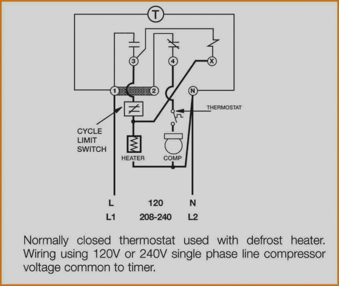
38 whirlpool defrost timer wiring diagram
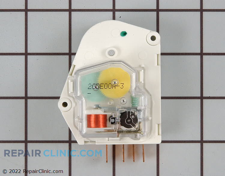
Sometimes after working on ADC, mainboards, jazz boards, genesis boards, utah boards, and beta boards, it's a relief to repair a fridge where the defrost is controlled by a good old standard timer. That is until you have to use the Whirlpool universal timer and have to re-read those "encoded" ins... This defrost timer is a genuine OEM replacement part sourced directly from the manufacturer for use refrigerators and freezers. The timer stops the compressor and evaporator fan motor at factory-set intervals. It starts the defrost heater's circuit to melt ice or frost on the evaporator to block airflow. If the defroster timer fails, ice will buildup, and the compressor will not run, which ...
W10822278 Wiring Diagram. Whirlpool Genuine OEM W Refrigerator Defrost Timer Kit. This timer will activate for 21 minutes every 8 hours. This timer kit is designed for both. Kenmore Refrigerator Defrost Timer W - This eight-hour defrost timer So I figured my model was too old, the wiring diagram was simalar to mine on.

Whirlpool defrost timer wiring diagram
Whirlpool Defrost Timer Wiring Diagram Source: static-assets.imageservice.cloud. READ 30 Amp 250 Volt Plug Wiring Diagram Database. Read electrical wiring diagrams from negative to positive plus redraw the routine being a straight line. All circuits are usually the same ~ voltage, ground, solitary component, and switches. Whirlpool Refrigerator Defrost Timer Wiring Diagram To properly read a cabling diagram, one provides to learn how the particular components in the system operate. For instance , when a module is powered up and it also sends out the signal of fifty percent the voltage in addition to the technician does not know this, he would think he offers a ... timer only advances when the compressor is running. After the timer measures an accumulated run time equal to a predetermined amount, the system will enter into the defrost cycle. This type of defrost is often referred to as a cumulative run-time defrost. Even the cumulative defrost systems fail to account for the number of times the door is opened
Whirlpool defrost timer wiring diagram. Whirlpool defrost timers only! When I was a little unsure about hooking those defrost timers up, where the timer motor wire went , #1 terminal or # 2 terminal. Whirlpool tech line gave me an easy way out: If the timer has a WHITE wire going to it ,the timer lead goes on #1 Anything else goes on #2 Model is Whirlpool ET20DK. There's also a green grounding wire on the original timer, what do I do with that? Levi for Model Number Whirlpool ET20DK. Answer Levi, unfortunately, the model number provided appears to be a partial model. However, if the wires going to the defrost timer include a white wire, the timer black wire will go to ... Wiring Diagram - Freezer ½ to 2 HP Single Phase. .. Set the correct time of day on the defrost timer. Do not set a cooler thermostat below the walk-ins design temperature or product Diagram 9 - Typical Wiring Diagram for Single with Defrost Timer Only.Jul 02, · I can increase the defrost time (Grasslin timer), but don't believe it will be ... In this video you can learn about the defrost timer wiring diagram of a frost free refrigerator and circuit diagram Step by step details about the function o...
Defrost Timer - Whirlpool W10822278 - The Defrost Timer (Defrost control) ... I found a wiring diagram folded up and stored in the grill in the bottom of the front of the frig that helped me determine this. you will need to be able to read a wiring diagram but I found this situation to be simply a matter of matching examples of pictures (line ... Refrigerator Defrost Timer Wiring Diagram Collection. refrigerator defrost timer wiring diagram - A Beginner s Overview of Circuit Diagrams A very first look at a circuit diagram may be confusing, however if you can check out a train map, you can review schematics. The function is the same: getting from factor A to point B. Literally,… I need a wiring diagram for Whirlpool refrigerator timer. The refrigerator M/N is W4TXNWW003, S/N VS23873283. Contractor's Assistant: Can you guesstimate how old your Whirlpool is? And just to clarify, what's the exact model? Defrost Timer Kit No. is 482493. Probably older than 5 years. Model No. above was on the plate. TIMER. Nov 14, · Defrost Timer Whirlpool Refrigerator Location - here you are at our site, this is images about defrost timer whirlpool refrigerator location posted by Benson Fannie in Wiring category on Nov 14, You can also find other images like wiring diagram, parts diagram, replacement parts, electrical diagram, repair manuals, engine ...
Whirlpool Defrost Timer Wiring Diagram from i.pinimg.com Print the wiring diagram off plus use highlighters in order to trace the signal. When you use your finger or perhaps follow the circuit with your eyes, it is easy to mistrace the circuit. Wiring Diagram Manualzz. 318 Icm Defrost Timer Manualzz. Original Service Manual. Whirlpool Installation Instructions For 482493 Defrost Timer Kit 1997 Sm Service Manual Schematics Eeprom Repair Info Electronics Experts. 38byc 018 060 60 Hertz Wiring Diagrams Manualzz. Paragon 632 20 Defrost Timer. Washing Machine Timer Online. 7 wire washing machine timer connection switch wiring diagram whirlpool defrost direct drive washer agitator reset a cabrio 6 व श ग stops during 3 machines how to read diagrams lxr7144eq1 resources online residential automatic kenmore 110258424 schematic diagnostics belt help appliance aid double circuit older top load midmark m7 kit installation guide for ... W10822278 Wiring Diagram. Kenmore Refrigerator Defrost Timer W - This eight-hour defrost timer So I figured my model was too old, the wiring diagram was simalar to mine on. I do not have a wiring diagram. ANSWER Hello Ken, You will need to connect the black jumper wire on the defrost timer W to pin. Whirlpool W Refrigerator Defrost Timer ...
Whirlpool Refrigerator Wiring Diagram - whirlpool double door refrigerator wiring diagram, whirlpool fridge freezer wiring diagram, whirlpool fridge thermostat wiring diagram, Every electrical arrangement consists of various distinct parts. Each part ought to be placed and linked to different parts in specific manner. If not, the structure won't function as it should be.
Paragon Defrost Timer Wiring Diagram. Whirlpool Refrigerator Water Line Diagram. 3 Wire Defrost Termination Switch Wiring Diagram. Lg Inverter Refrigerator Wiring Diagram. Ge Monogram Refrigerator Wiring Diagram. Kenmore Refrigerator Compressor Wiring Diagram. Frigidaire Refrigerator Compressor Wiring Diagram. Lg Double Door Refrigerator Wiring ...
timer only advances when the compressor is running. After the timer measures an accumulated run time equal to a predetermined amount, the system will enter into the defrost cycle. This type of defrost is often referred to as a cumulative run-time defrost. Even the cumulative defrost systems fail to account for the number of times the door is opened
Whirlpool Refrigerator Defrost Timer Wiring Diagram To properly read a cabling diagram, one provides to learn how the particular components in the system operate. For instance , when a module is powered up and it also sends out the signal of fifty percent the voltage in addition to the technician does not know this, he would think he offers a ...
Whirlpool Defrost Timer Wiring Diagram Source: static-assets.imageservice.cloud. READ 30 Amp 250 Volt Plug Wiring Diagram Database. Read electrical wiring diagrams from negative to positive plus redraw the routine being a straight line. All circuits are usually the same ~ voltage, ground, solitary component, and switches.


![[DIAGRAM] Refrigerator Defrost Timer Wiring Diagram FULL ...](https://tops-stars.com/wp-content/uploads/2017/09/walk-in-freezer-defrost-timer-wiring-diagram-heatcraft-walk-in-inside-walk-in-freezer-defrost-timer-wiring-diagram.jpg)


0 Response to "38 whirlpool defrost timer wiring diagram"
Post a Comment