39 ford ballast resistor wiring diagram
Because of this, I added a backup ignition box using a Duraspark box. When doing this, I studied the Ford Duraspark wiring diagrams typical of the stock early/mid eighties Ford Duraspark II (blue connector) setups. As I remember, a full 12V goes to the box/dist; but a resistor is used just for the Ford coil of that era. JavaScript seems to be disabled in your browser. For the best experience on our site, be sure to turn on Javascript in your browser · How would you like to be shut in a chamber with temperatures of up to 3000°C, splashed with petrol and given a 30,000 volt electric shock 25 times a second, ...
Help With Locating Ballast Resistor On '83 - posted in 80-96 Ford Truck: I've done a fairly thorough electrical check and found I'm not getting the roughly 6-9V hot into the ignition coil. This, of course, after I already replaced the ignition module and the distributor pick-up I know the hot-into-coil circuit is the issue 'cuz running 12V hot from battery to ignition coil starts truck fine ...
Ford ballast resistor wiring diagram
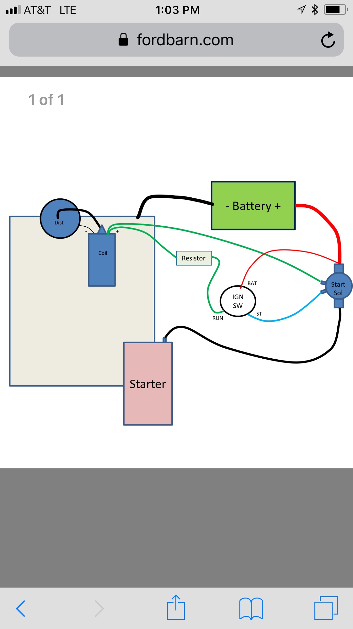
PerTronix Electronic Ignition Systems can upgrade the spark in your system for a noticeable gain in horsepower. Free shipping on most orders. A resistor wire or ballast resistor may or may not be included in the original equipment. The typical automotive ignition system prior to 1974 consisted of a coil and ballast resistor with breaker points to interrupt the current flow when a spark was needed. Diagram Wiring Diagram Ballast Resistor Ignition Coil Full Version Hd Quality … Ballast resistor or in the case of stock Ford wiring, a resistor wire, cuts the voltage to the coil to 6volts in the RUN position of the ignition key (longer coil life). The coil gets a full momentary 12volts in the START position to give you a hotter spark during start ups. "If it is not right do not do it; if it is not true do not say it.".
Ford ballast resistor wiring diagram. January 13, 2019 - Diagram 65 Mopar Ignition Wiring Full Version Hd Quality Ajaxdiagram Koine It. Bypassing Ballast Resistor For A Bos Only Mopar Forum. Anything I Can Substitute For A Ballast Resistor Ford Truck Enthusiasts Forums. Ignition Issue 71 302 Only Runs In Crank Position Ford Mustang Forum. How To Wire Mid 1970s Through 1980s Ignition Systems Retroing ... Click here for more 8n stuff https://etsy.me/37E0tjX Some good tips on how to go about trouble shooting your 8N when it won't start. I show how to trace down... Assuming that you are talking about the placement of the OEM ballast resistor on a 6v frontmount, the wiring diagram Bob posted is correct. The resistor itself goes on top of the terminal block. If ANY of the above assumptions are incorrect, post back w/ the correct info. 50 Tips
Ignition Coil Ballast Resistor Wiring Diagram Led Fluorescent, Led Tubes, Rx7, ... Finally Done, Cluster Swap w/ Tach - Ford Truck Enthusiasts Forums. 23 May 2011 — If I am reading my schematic correctly, it looks like the resistor wire powers more than just the coil. So to power my new coil with a ... October 19, 2018 - A lot of fellas have asked me this question over the years. When you don't do this stuff regularly (nobody does anymore) it can be easy information to Step 3. Cut a piece of wire long enough to reach from the other terminal of the ballast resistor to the "Bat", "+" or "B+" terminal of the coil. Strip 1/2 inch of insulation from each end of this wire and crimp a connector onto each end. Connect the wire to the unused terminal of the ballast resistor and to the previously identified terminal of ...
To connect a Ford gray remote-mount TFI unit, looking directly at the module as shown. Pin #1 is connected to ... run through a ballast resistor or wire. Bypass any resistance unit to provide full 12V key ON power to the ... Ford TFI gray remote-mount module wiring diagram: Note: The TFI module will fire the coil on the rising edge ... Also, for some odd reason there ... into the resistor wire. The only red/yellow wires I see on my wiring diagram go to the oil pressure and charge indicator lights. In my wiring diagram the red/yellow gets power from the accessory terminal on the ignition switch, not the ignition terminal. Just another crazy wiring modification from Ford I ... ballast resistor. Connect the Red/Green wire to the output side of the ballast resistor. 5. Next connect the white wire to the “I” terminal on the starter solenoid. Note: If the solenoid being used do es not have an “I” terminal, the white wire must be connected to the “S” terminal of the solenoid. 6. May 20, 2019 - Paraphrasing Tool helps, Paraphrase Online easily, Best Tool for any writer who rewrites web content, papers, best word changer
January 31, 2011 - The resistor was put in their by ford to keep the ignition pints from burning up the contacts, I would check with Petronix on this, last I checked with their support no ballast resistor is necessary and replacing the pink resistor wire with a straight copper wire, or using a relay so that the ...
Disconnect the connections at the ballast resistor. Measure the voltage (or check with a test light) the voltage between the single wire and ground. If there is ...
Official Site of Painless Performance, American Made wiring harnesses for your hot rod, street rod, muscle car, off-road and everything in between. Wire it once and wire it right with Painless.
22 Feb 2019 — During starting however, the ballast resistor wire is by-passed allowing full ... These diagrams indicate there are two feed cables to coil ...
Ford Ballast Resistor Wiring Diagram. Print the wiring diagram off plus use highlighters to trace the signal. When you make use of your finger or perhaps the actual circuit with your eyes, it is easy to mistrace the circuit. 1 trick that We 2 to printing a similar wiring plan off twice.
Ford started using the ballast resistor wire with the 1960 models. How to wire a doorbell diy live demo and wiring diagram duration. 2 wires wrong on ballast resistor 351w wiring lively projects. For 1961 1967 ford econoline ballast resistor smp 29344vk 1964 1962 1963 1965 fits.
August 26, 2016 - The ignition coil cannot get proper voltage if the ballast resistor is broken. Signs are a crank without a start or a start and an immediate stall.
Step 4: Install Ballast Resistor. Set the ballast resistor up to the firewall and screw the clamps in place. Step 5: Connect Wires to Positive. Strip the end of the positive wire from the ignition, and connect it to the positive end of the resistor. From the other terminal on the resistor a wire goes to the positive on the coil.
November 16, 2008 - Hey guys, having a few difficulties with my KE36 pano, Now its got a stock 3k and all that, now when I got the car the coil had been removed, therefore I have no idea where wires go lol, I have a 4 Pin relay hooked up, its got earth wire, 12v battery wire, and a wire going to positive side ...
October 28, 2004 - Online forums for Capri Owners · It is currently Mon Jul 19, 2021 3:40 pm
Ford Ballast Resistor Wiring Diagram from cimg3.ibsrv.net. Print the electrical wiring diagram off plus use highlighters in order to trace the signal. When you use your finger or the actual circuit together with your eyes, it is easy to mistrace the circuit. 1 trick that I use is to print out exactly the same wiring plan off twice.
April 7, 2017 - 1973 - 1979 F-100 & Larger F-Series Trucks - Ballast resistor or resistor wire? - I'm driving a 1974 ford f250 360 pre-electronic ignition, just replaced the ignition with the newest generation pertronix module and coil- what a huge difference in performance and mileage.
Ignition Coil Ballast Resistor Wiring Diagram. Print the cabling diagram off plus use highlighters to be able to trace the circuit. When you use your finger or even follow the circuit together with your eyes, it is easy to mistrace the circuit. 1 trick that We use is to print the same wiring picture off twice.
ford f wiring harness ford f engine diagram ford ford f voltage regulator ford f wiring diagram ford. Results 1 - 48 of 98 SEE FIT CHART IN PHOTOS. $ Ford Lincoln Mercury Edsel Thunderbird Ignition Coil Resistor NOS NORS USA MADE COIL BALLAST RESISTOR EDSEL,LINCOLN,MERCURY,FORD TRUCK . NEW SET of Motorcraft Spark Plug Wires Edsel V8 D6PZBA.
This Video explains how the Ballast Resistor Works.For additional How-to Tutorials Visit our Website: http://www.howstuffinmycarworks.com
I need to follow up on the ballast resistor as i dont think i have one. Ignition coil ballast resistor wiring diagram welcome to my interne...
That depends upon a few things ... retard wire. IF the coil has .08 primary ohms or less, then it will need a ballast resistor for continuous running; for drag racing, short term usage, usually not. Now if the coil has .14 primary ohms or more then it would not need a ballast resistor at any time. ... The standard Ford TFI "E" core ...
How to fix a fan that doesn't work on low. If your interior AC/ Heat fan is not working on low, or one of the fan settings isnt working, then you probably ne...
The ballast resistor get's installed on the wire from the ignition switch to the positive side of the ignition coil and it's the wire that is hot when the key is on run not start. the start coil wire should still have 12 volts. One second and I'll pull up the wiring diagram. Ford Ignition Wiring Diagram - wiring diagram plymouth reliant ...
Due to the EU's Global Data Protection Regulation, our website is currently unavailable to visitors from most European countries. We apologize for this inconvenience and encourage you to visit www.motortrend.com for the latest on new cars, car reviews & news, concept cars and auto show coverage, ...
About Press Copyright Contact us Creators Advertise Developers Terms Privacy Policy & Safety How YouTube works Test new features Press Copyright Contact us Creators ...
23 Mar 2010 — The parts list for my 60 f100 showes a ballest resistor wire rather ... If you look at the simple diagram below, the ballast resistor would ...
Ballast resistor or in the case of stock Ford wiring, a resistor wire, cuts the voltage to the coil to 6volts in the RUN position of the ignition key (longer coil life). The coil gets a full momentary 12volts in the START position to give you a hotter spark during start ups. "If it is not right do not do it; if it is not true do not say it.".
A resistor wire or ballast resistor may or may not be included in the original equipment. The typical automotive ignition system prior to 1974 consisted of a coil and ballast resistor with breaker points to interrupt the current flow when a spark was needed. Diagram Wiring Diagram Ballast Resistor Ignition Coil Full Version Hd Quality …
PerTronix Electronic Ignition Systems can upgrade the spark in your system for a noticeable gain in horsepower. Free shipping on most orders.


0 Response to "39 ford ballast resistor wiring diagram"
Post a Comment