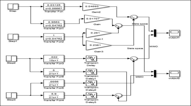
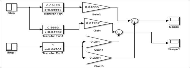
37 block diagram to state space
To construct the reduced state diagram, first, build the state table for the given state diagram, find the equivalent states, remove the redundant state, draw the reduced state table and finally construct the state diagram. First, the information in the state diagram is transferred into the state table as shown below. SOCRATES Block Diagram Image: NCIT/AES Break Board Model of SOTA - Image: NCIT. The main payload of SOCRATES is SOTA - the Small Optical Transponder that will be used to demonstrate a compact laser communications terminal for use on satellites, microsatellites and nanosatellites.
By definition, the bubble diagram is a freehand diagrammatic drawing made by architects and interior designers to be used for space planning and organization at the preliminary phase of the design...

Block diagram to state space
Create and analyze state-space models using MATLAB ® and Control System Toolbox™. State-space models are commonly used for representing linear time-invariant (LTI) systems. This video shows how you can: Create state-space models. Combine state-space models with other model types, such as transfer functions, to develop more complex system models. In a block diagram, the state-space system looks like General Case. For a single-input single-output transfer function G ( s) = b n − 1 s n − 1 + ⋯ + b 1 s + b 0 s n + a n − 1 s n − 1 + ⋯ + a 1 s + a 0 + d, we can verify that Misplaced \hline Misplaced \hline realizes G ( s). This realization is called the controllable canonical form. It allows the conversion of the system into a state-space representation. It is similar to a block diagram or signal-flow graph, with the major difference that the arcs in bond graphs represent bi-directional exchange of physical energy, while those in block diagrams and signal-flow graphs represent uni-directional flow of information.
Block diagram to state space. State Space, Part 2: Pole Placement. From the series: State Space. Brian Douglas. This video provides an intuitive understanding of pole placement, also known as full state feedback. This is a control technique that feeds back every state to guarantee closed-loop stability and is the stepping stone to other methods like LQR and H infinity. Download scientific diagram | Block diagram representation of the state space equations. from publication: State-Space model of a mechanical system in MATLAB/Simulink | This paper describes ... The equivalent block diagram is shown below. Similarly, you can represent the positive feedback connection of two blocks with a single block. The transfer function of this single block is the closed loop transfer function of the positive feedback, i.e., $\frac{G(s)}{1-G(s)H(s)}$ Block Diagram Algebra for Summing Points State Space, Part 1: Introduction to State-Space Equations. Let's introduce the state-space equations, the model representation of choice for modern control. This video is the first in a series on MIMO control and will provide some intuition around how to think about state variables and why this representation is so powerful. Having a solid ...
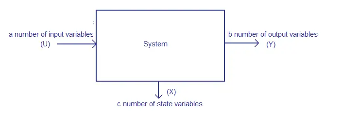
It looks like you want to extract the a,b,c,d matrices of the ss object that is returned by connect(), but ss2tf is used to go in the other direction, i.e., take the state space matrices and convtert to a transfer function.. Block diagram representation of the linear state-space equations The most general state-space representation of a linear system with p {\displaystyle p} inputs, q {\displaystyle q} outputs and n {\displaystyle n} state variables is written in the following form: [14] A block diagram representing the real-time implementation of the proposed MRAS-based current estimation technique is shown in Fig. 12. This method consists of two main sub-systems. Implementation of MRAS in DSPACE. The state-space model of the boost converter shown in Fig. 3 is implemented in real-time in DSPACE 1104 using MATLAB. The actual ... Page title block. The page title block is present in the footer of the schematic page. It is a good practice to fill in all the required details such as page size, update date, revision, document number, name/function of the circuit, and company disclaimer. An example of the title block is shown below.
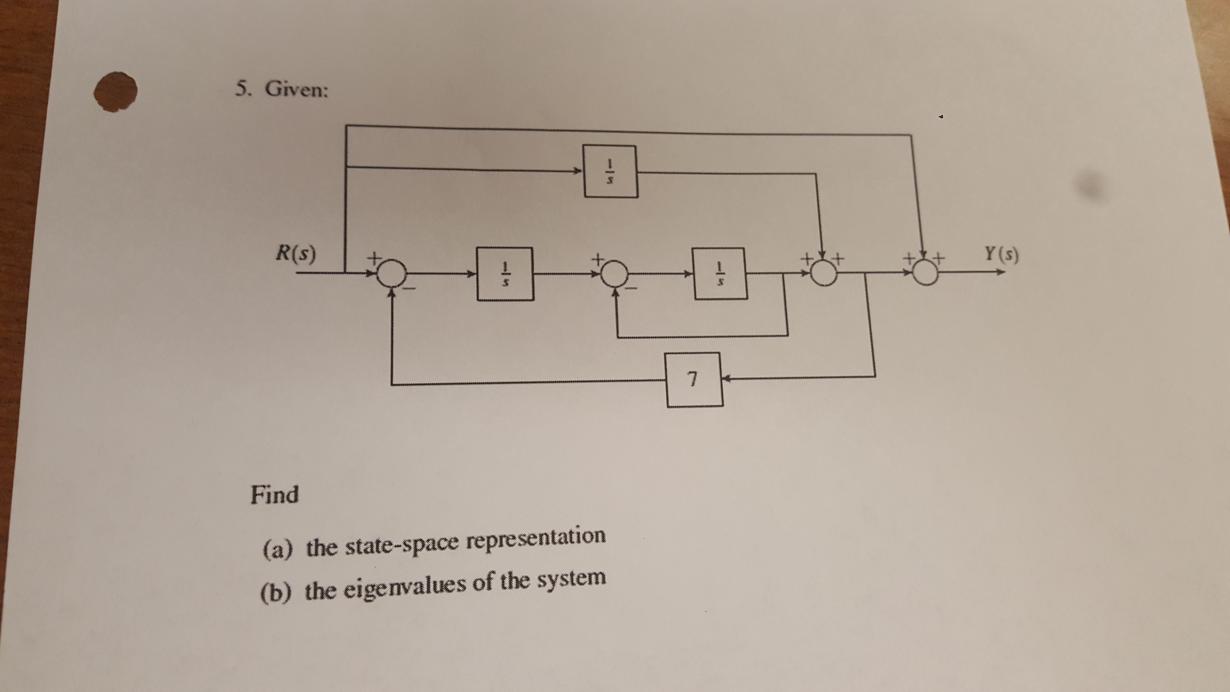
MAPSS can be used to generate state-space linear models, from which the user may create a piecewise linear controller. MAPSS can also run transient simulations. This capability allows the user to test the performance of their algorithms on a validated, and verified, generic engine model. Diagram of the C-MAPSS Engine This section explains the block diagram of the function generator along with its working. Below is the block diagram picture: Block Diagram. For a function generator construction, a frequency controlling network is used where is frequency is regulated by the change in the current's magnitude level. An integrator is used where this is driven ... A matrix block diagram of the state estimate covariance time update P - (t) and standard (non-Joseph stabilized) measurement update P + (t) calculations and of the filter gain update K(t) calculations is shown below. The inputs are the process noise covariance Q(t) and the measurement noise covariance R(t). State Space Representation) The block diagram for a discrete time system is given in Fig. 5.35. Develop a state space representation for the system using the form. Clearly identify the A,B, C, and D matrices for your implementation. Jan 13 2022 03:09 AM.
AQUA
It controls concurrent access by performing the operations in a scheduled way that it receives the transaction. Thus, it ensures that the database remains in the consistent state before and after the execution of a transaction. File Manager - It manages the file space and the data structure used to represent information in the database.
Differential Equation - State Space | ShareTechnote
Telephone, radio, television, internet, and military applications use satellite communications. Believe it or not, more than 2000 artificial satellites are hurtling around in space right above your heads. Satellite Communication Block Diagram. Need for Satellite Communication

Structure model of discrete state space controller with ...
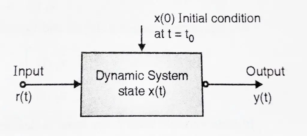
A block diagram is a visualization of the control system that uses blocks to represent the transfer function and arrows representing the different input and output signals. Transfer Function The transfer function is a convenient representation of a linear time-invariant dynamical system.

Satellite in orbit
The block diagram for this decomposition is given in Figure 3.1. U(s) V(s) V(s)/U(s) Y(s)/V(s) Y(s) Figure 3.1: Block diagram representation for (3.17) Equation (3.17a) has the same structure as (3.6), after the Laplace transformation is applied, which directly produces the state space system equation identical to (3.9). It remains to find ...

Block diagram schematic of Model Predictive Control ...
The block diagram of TCR system along with the communication between the equipment and a personal computer is illustrated in Figure 1. FIGURE 1. ... Therefore, the nonlinear state-space model of 3-DOF TCR systems is introduced as the following similar model to that given in Roman et al. ...

Monochrome, Unesco World Heritage Site, National Trust, Water Landscape, Giant's Causeway, County Antrim, Northern Ireland.
Rule 6 − Repeat the above steps till you get the simplified form, i.e., single block. Note − The transfer function present in this single block is the transfer function of the overall block diagram. Example. Consider the block diagram shown in the following figure. Let us simplify (reduce) this block diagram using the block diagram ...
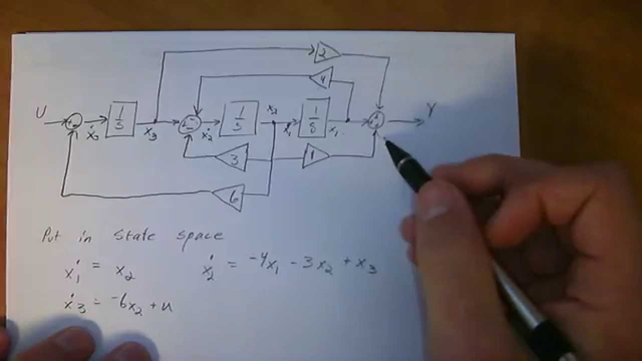
block diagram to state space - YouTube
As it is based on the same state variables like the time-optimal controller, its block diagram will be very similar, as Figure 13 shows. Because the controlled system (plant) in the example is not an astatic type, when the output variable achieves its target value (i.e. being equivalent to a desired value, R and both, err and derr become zero ...
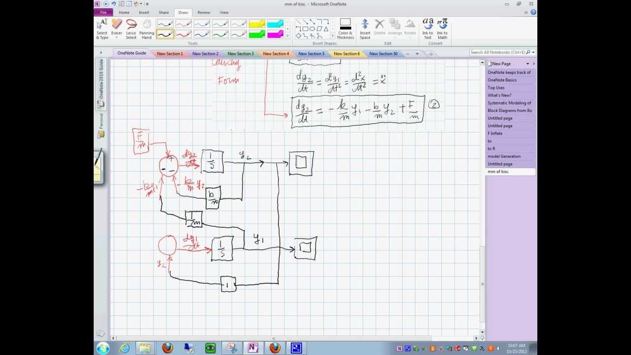
Block Diagrams from State Space Equations. 25102012_1010 ...
Apple's patent FIG. 3 below is a block diagram of a system that uses correlated motion to select a motion tracking state; FIG. 9 illustrates various reference frames and notation for relative pose ...

Average state block diagram of buck converter | Download ...
Aug 13, 2017 · The block diagram of a function generator is given in the figure. In this instrument, the frequency is controlled by varying the magnitude of the current that drives the integrator. This instrument provides different types of waveforms (such as sinusoidal, triangular and square waves) as its output signal with a frequency range of 0.01 Hz to ...
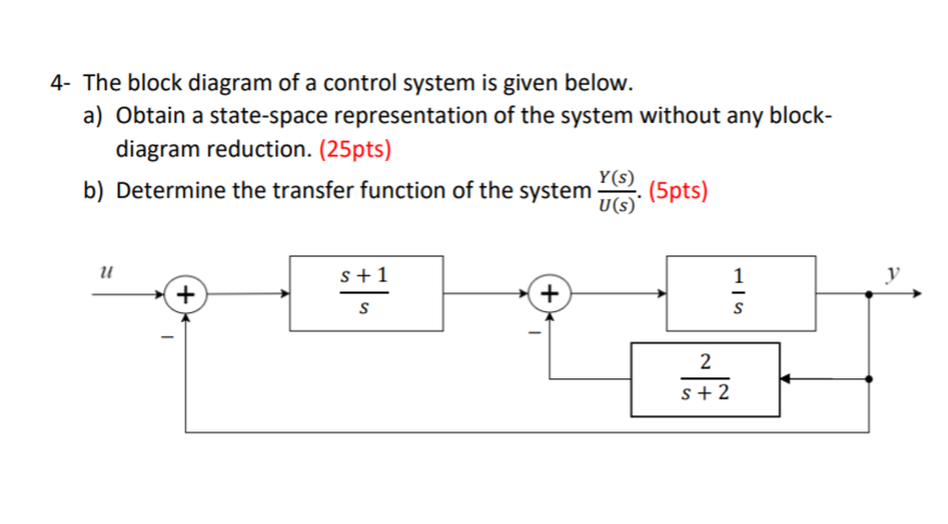
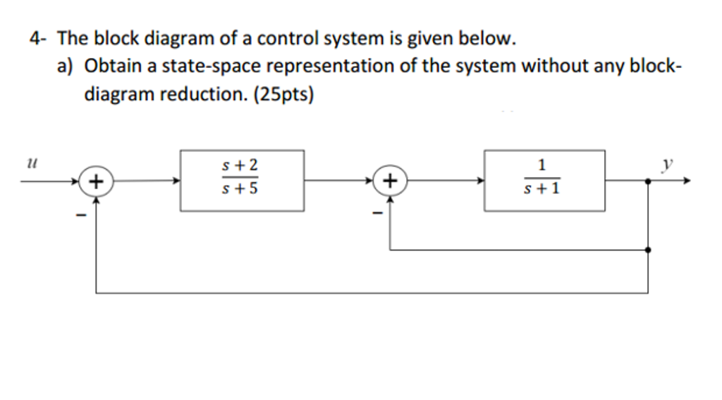
Solved: 4- The Block Diagram Of A Control System Is Given ...
3 Block Diagrams 4 Signal Flow Graphs 5 Modelling A Control System 6 Time Response Analysis Of Control Systems 7 Stability Analysis Of Control Systems 8 Compensation Of Control Systems 9 Introduction To State Space Analysis Of ConTrol Systems 11 Solution Of Problems Using Computer 12 Classified Solved Examples. linear control system by bs manke pdf

United States Supreme Court Original Historical
Conda and conda-forge. The easiest way to get started with the Control Systems library is using Conda.. The Control Systems library has been packages for the conda-forge Conda channel, and as of Slycot version 0.3.4, binaries for that package are available for 64-bit Windows, OSX, and Linux.. To install both the Control Systems library and Slycot in an existing conda environment, run:

Visited the Empire State Building on our trip to New York in February.
Feb 04, 2020 · To place objects on the block diagram, simply drag and drop them from the Functions palette. The Functions palette automatically appears when you right-click anywhere on the block diagram workspace. It contains functions, constants, structures, and some subVIs. Notice the two buttons on the top of the Functions palette. The Thumb Tack pins the Functions …

Block diagram of PID controller in state-space ...
Draw the block diagram of the state space representation of the second order differential uation in the previous . The result is in Fig. E4.2. It is quite easy to understand if we take note that the transfer function of an integrator is 1/s.
Study on Dynamics of Saponification Process Using State ...
State Space diagram for Hill Climbing. The state-space diagram is a graphical representation of the set of states our search algorithm can reach vs the value of our objective function(the function which we wish to maximize). X-axis: denotes the state space ie states or configuration our algorithm may reach.

Block Diagram of State Feedback Controller | Download ...
This block diagram is solved examples below solved in simulink is required to solve the blocks. The diagram reduction technique will solve this model to ensure that may specify a crossed circle....
Study on Dynamics of Saponification Process Using State ...
[A,B,C,D]=LINMOD ('SYS') obtains the state-space linear model of the system of ordinary differential equations described in the block diagram 'SYS' when the state variables and inputs are set to...

GATE ECE 1996 | State Space Analysis Question 4 | Control ...
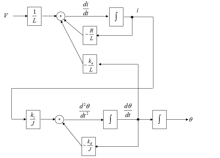
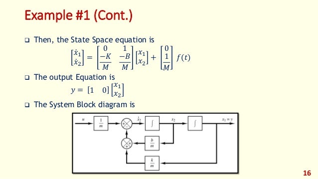
Feb 12, 2020 · Expressing the last equations in vector-matrix form, we get the state-space representation of the system as: At this point, we can create an equivalent block diagram of the systemof Figure 1(a) to help visualize the state variables.We draw three integral blocks as shown in Figure 1(b) and label each output as one of the state variables, xi(t ...
State space analysis, state of a system, state variables.
A Block Flow Diagram (BFD)—sometimes referred to as an Iconic Flow Diagram—provides an outline of a process on just one or two sheets. It is not to scale and will contain only very limited engineering and process information. A BFD generally consists of the following: • Symbols for the larger equipment items or for groups of equipment.

5: Block diagram of SISO state space model | Download ...
is directly derived from the State diagram. The present state, and the corresponding next state when the input X=0 and X=1 are shown in separate columns respectively.

Control Tutorials for MATLAB and Simulink - Introduction ...
StateSpaceControl. This library defines StateSpaceController; a template class which implements a multi-input, multi-output state space feedback controller with reference tracking, state estimation and integral control.. The architecture of the controller implemented by this library is as follows: If everything in this block diagram makes perfect sense to you then, great!

Scotswood Bridge, Newcastle/Gateshead, Tyne & Wear, England.
A block diagram majorly comprises rectangle shapes known as blocks and the straight lines with arrows at the end. While the blocks represent the key elements of the entire process, the arrowed lines show the relationship between the two objects and the direction the data, information, processing, signals, or the electric current flows in.

Block representation of the state-space model in Simulink ...
Block Diagrams with Transfer Functions: Block Diagram: L26: State Space Models: Reactor State Space: State Space Simulation: L27: Second Order Systems with Graphical Fitting: Second Order Estimation: Graphical: On/Off Control: L28: Second Order Optimization: Second Order Estimation: Optimization: Second Order Regression: L29: Simulation of ...

How to get the state-space model of a dynamic system - x ...
It allows the conversion of the system into a state-space representation. It is similar to a block diagram or signal-flow graph, with the major difference that the arcs in bond graphs represent bi-directional exchange of physical energy, while those in block diagrams and signal-flow graphs represent uni-directional flow of information.

The view from Kerry Park is just spectacular. Especially if you’ve watched Grey’s Anatomy in your life 😛
In a block diagram, the state-space system looks like General Case. For a single-input single-output transfer function G ( s) = b n − 1 s n − 1 + ⋯ + b 1 s + b 0 s n + a n − 1 s n − 1 + ⋯ + a 1 s + a 0 + d, we can verify that Misplaced \hline Misplaced \hline realizes G ( s). This realization is called the controllable canonical form.

FF7a
Create and analyze state-space models using MATLAB ® and Control System Toolbox™. State-space models are commonly used for representing linear time-invariant (LTI) systems. This video shows how you can: Create state-space models. Combine state-space models with other model types, such as transfer functions, to develop more complex system models.

Feedback control. (a) Proportional control and (b) state ...
Control System - State Space Analysis - ElectronicsGuide4u

1-Block-diagram representation of a state-space model ...

Scotswood Bridge, Newcastle/Gateshead, Tyne & Wear, England.
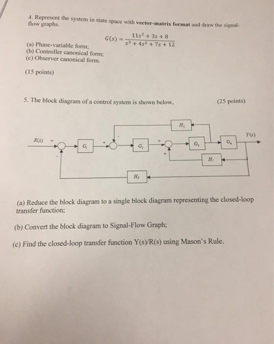
Solved: 4. Represent The System In State Space With Vector ...

Block diagram of the algoritm for the automatic ...

Monochrome, Church Architecture, St. Mary's Cathedral, Sydney, New South Wales, Australia.
Modern Control - Lec07 - State Space Modeling of LTI Systems
Solved: State Space Controls Problem (Block Diagram To Sta ...

Block diagram of PWR state space model simulation in ...
Solved: The Block Diagram Of A Control System Is Given Bel ...

Solved: Simplify The Block Diagram Shown In Figure 3-50 An ...
0 Response to "37 block diagram to state space"
Post a Comment