37 glowshift gauges wiring diagram
Glowshift · temp gauge wiring diagram. Tinted series oil pressure gauge for product numbers: Before you search for a. Connecting the power wire harness. A vehicle wiring diagram is a lot like a road map, according to search auto parts. Source: lh6.googleusercontent.com. GlowShift Gauges is world renowned for providing exceptionally crafted and competitively priced automotive gauges with an extensive variety of styles and options. Over the years, GlowShift's lineup of performance gauges and gauge pods has grown exponentially to include many of the most sought after gauges in the automotive market.
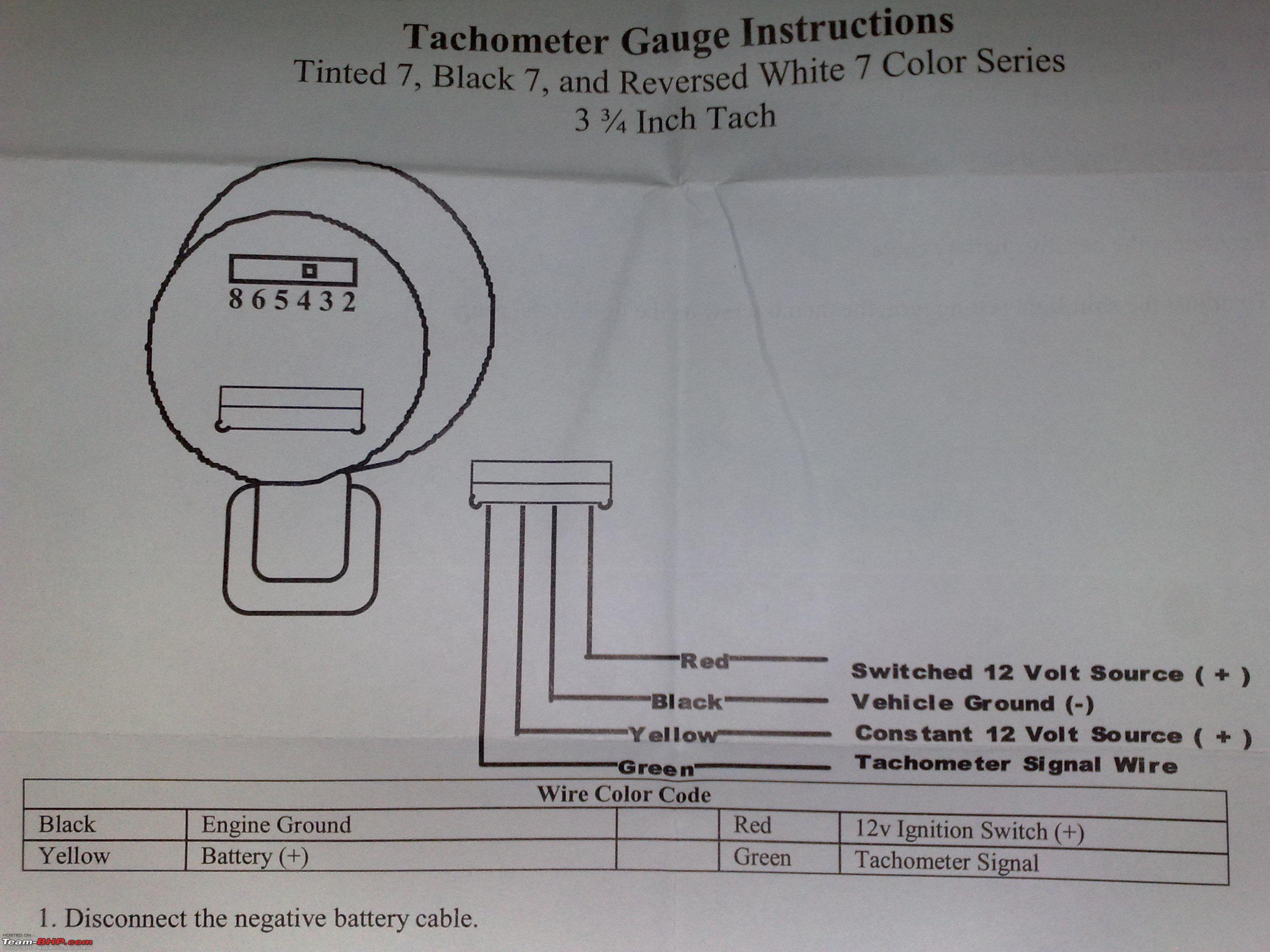
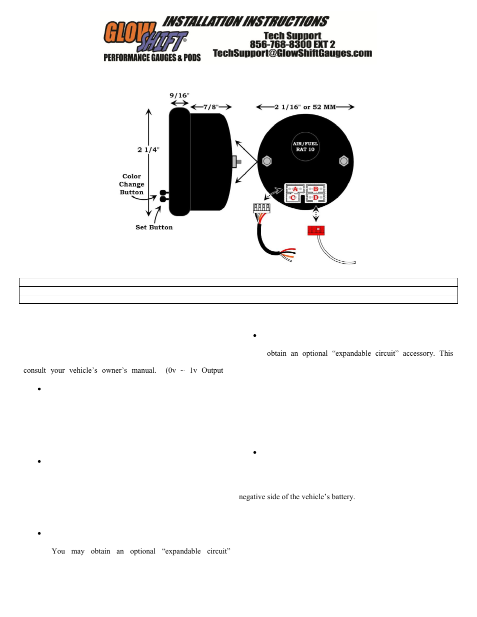
provides an additional fused power wire for accessories such as gauges. The expandable circuit is available for purchase at www.GlowShift.com. power to the gauge for proper calibration. 3. Using automotive grade wiring (18 gauge); connect the yellow wire to a positive 12 volt constant (un-switched) source either on the vehicle or in the fuse box.
Glowshift gauges wiring diagram
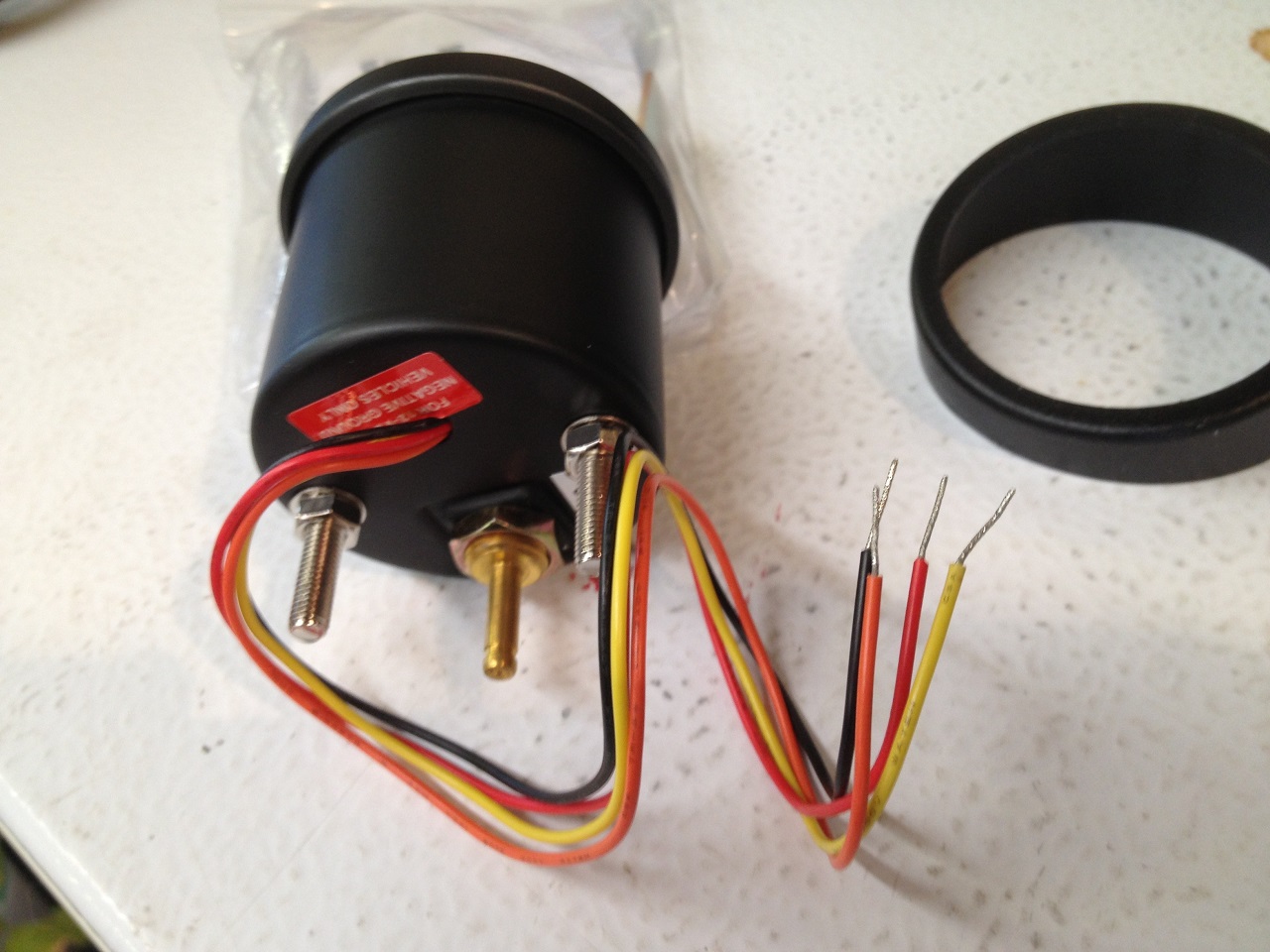
i got them working. the colors weren't the same as the manual said but i traced them on the diagram and got the right ones. thanks again. EDIT: for anyone that is looking for what i was, do as DeathBySpray said and go with the headlight switch. i was replacing my gauge cluster panel with Glowshift's to hold my 2 gauges so the headlight switch was right there for me. looking at the electrical ... GlowShift Gauges, LLC 444 Commerce Lane Suite A West Berlin, NJ 08091 GlowShift.com Additional Information • The supplied optional gauge visor is intended to be placed on the gauge so that the thickest part is at the top, creating a cover over the gauge to help keep sun glare off of the gauge face. GlowShift Gauges, LLC 444 Commerce Lane Suite A West Berlin, NJ 08091 GlowShift.com Gauge Wiring 1. In order to test for power, reconnect the Negative Battery Terminal. 2. It may be necessary to remove the Vehicle Trim and/or Kick Panels in order to gain access to the vehicle's Fuse Box. 3.
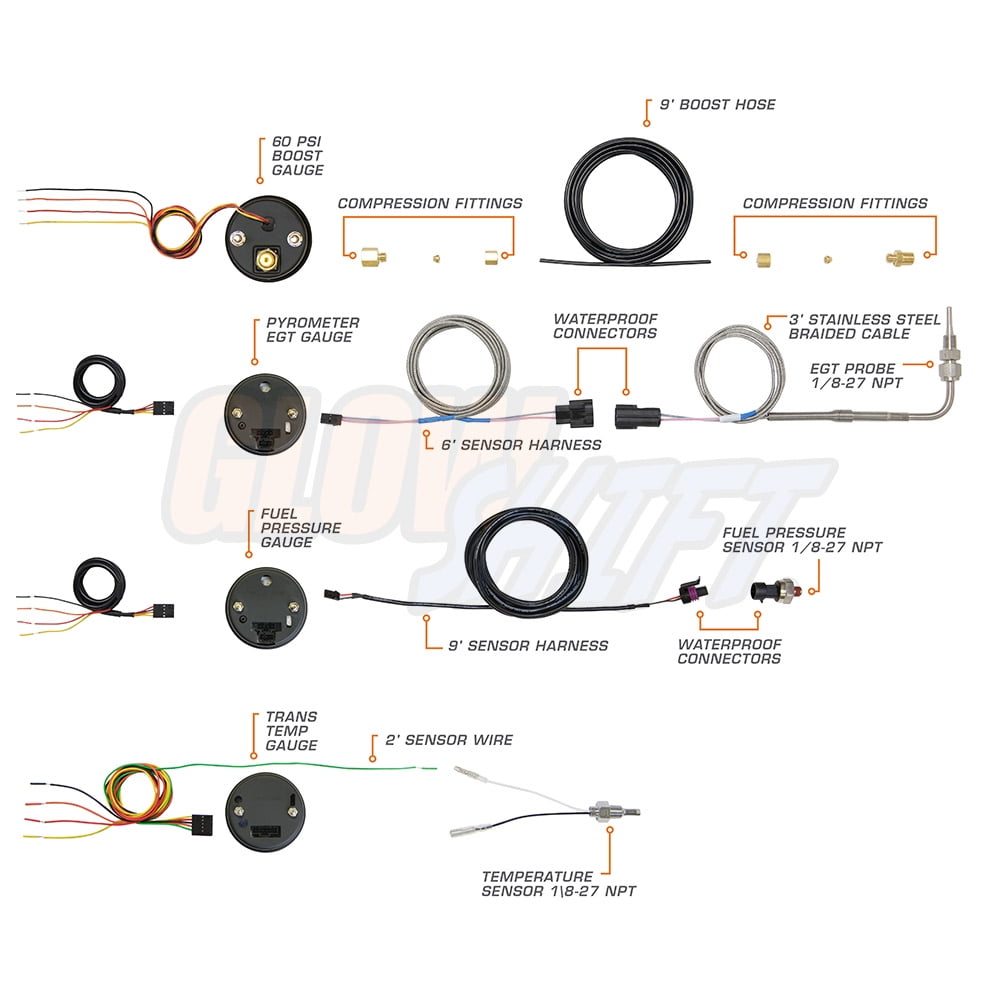
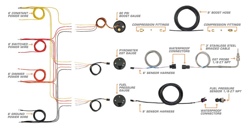
Glowshift gauges wiring diagram. Glowshift Boost Gauge Wiring Diagram. 1. Disconnect the negative battery cable. Gauge Installation. 2. Connect the boost line to the gauge using the female compression fitting. Once this is connected. GlowShift's Wiring Harnesses are comprehensive wiring packages that allow you to easily wire multiple temperature or pressure gauges from one ... GlowShift Gauges, LLC 444 Commerce Lane Suite A West Berlin, NJ 08091 GlowShift.com Gauge Wiring 1. In order to test for power, reconnect the Negative Battery Terminal. 2. It may be necessary to remove the Vehicle Trim and/or Kick Panels in order to gain access to the vehicle's Fuse Box. 3. The wiring diagram is easy to follow, but the instructions weren't clear as to. Our GlowShift support page delivers a multitude of helpful tools that are essential for our GlowShift customers. Whether you need to access GlowShift install. Elite 10 Color Transmission Temperature Gauge. For Product Numbers: GS- ET12 & GS-EWT Wire Harness Color Code. Using automotive grade wiring (18 gauge); connect the red wire to a positive 12 volt ignition (switched) source. It may be connected to the fuse panel, an accessory wire, or any positive 12 volt source that turns on and off with the ignition. 5. Using automotive grade wiring (18 gauge); connect the black wire to any good (unpainted) ground ...
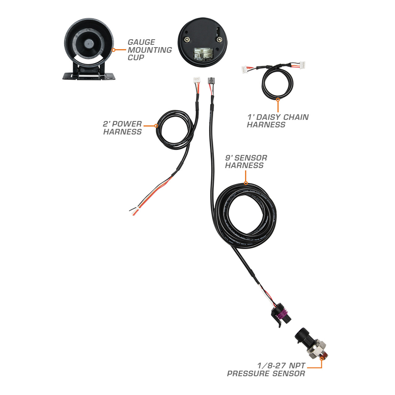
GlowShift Oil Pressure Gauges display your vehicle's oil pressure levels from 0 to 100 PSI depending on which version you select. Oil pressure gauges can be vital in ensuring the longevity of any car or truck. Monitoring your engine's oil pressure in real time will help ensure your bearings, crankshaft and other critical parts stay properly ... Glowshift Fuel Pressure Gauge Wiring Diagram wiring diagram is a simplified good enough pictorial representation of an electrical circuitIt shows the components of the circuit as simplified shapes and the aptitude and. Red Wire Connects to a Switched 12 Volt Source. Glowshift volt gauge wiring diagram. The ICON Pro RPM gauge connects to a NMEA-2000 network. Com readers as well as 2021 Honda ATV prices and specifications. The green wire reads the electrical pulses from the ignition. Rotate at a very high rate of speed. North Stonington CT 06359 USA. GlowShift Wiring Harnesses are comprehensive wiring kits equipped with power wires, sensor wires or both and are designed specifically for GlowShift Gauges. Each automotive gauge wiring kit features extended wiring lengths that make it even easier to install our gauges. You'll be able to run sensor lines for GlowShift temperature gauges ...
GlowShift Gauges, LLC 444 Commerce Lane Suite A West Berlin, NJ 08091 GlowShift.com Gauge Wiring 1. With your Oil Pressure Sensor Harness connected, plug in the Power Harness and place the gauge in the mounting location. 2. In order to test for power, reconnect the Negative Battery Terminal. 3. For Full Warranty Information Visit GlowShift.com 3 Gauge Wiring Kit Instructions 1. Red Wire - Connects to a Switched 12 Volt Source. This wire should be connected to an ignition source that turns power GlowShift's Wiring Harnesses are comprehensive wiring packages that allow you to easily wire multiple temperature or pressure gauges from one harness. 1. Disconnect the negative battery cable. Gauge Installation. 2. Connect the boost line to the gauge using the female compression fitting. Once this is connected. GlowShift.com. 5. Using automotive grade wiring (18 gauge), connect the yellow wire to a positive 12 volt constant (un-switched) source either on the.
Tinted Series Oil Pressure Gauge
Glowshift Gauge Wiring Diagram- One of the most hard automotive repair tasks that a mechanic or repair shop can acknowledge is the wiring, or rewiring of a car's electrical system.The trouble truly is that every car is different. next infuriating to remove, replace or repair the wiring in an automobile, having an accurate and detailed glowshift gauge wiring diagram is critical to the ...

Black 7 Color 60 PSI Exhaust Pressure Gauge
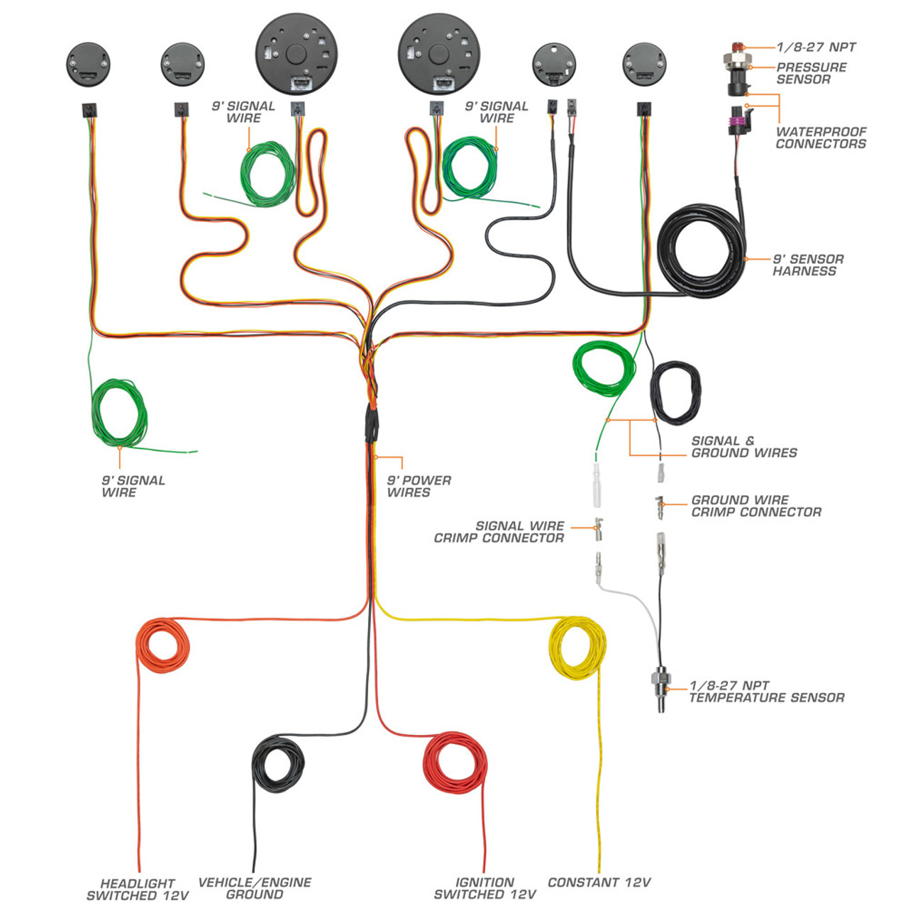
GlowShift's 7 Color Series 3 Gauge Wiring Kit is a complete wiring harness that allows you to easily wire 3 Tinted 7, Black 7 or White 7 Color Gauges from one harness. This wiring kit features both sensor and power wires combined for each gauge. This wiring kit is made with 20 gauge automotive grade wiring and features a length of 8' for the ...
Pre wiring my gauges need help asap please | Ford Powerstroke ...
and contact GlowShift Gauges. Boost/Vacuum Gauge Instructions Wiring Schematic Disconnect negative battery terminal before starting any work on the vehicle. 5. Route the Boost/Vacuum Line through the firewall from the engine bay, keeping it clear of any moving parts, heat sources, and kinks. Note: Be sure to use a grommet when routing the line
GLOW-SHIFT GAUGES
This GlowShift video shows you how to install our White 7 Color Series 6 Gauge Custom Dashboard Set to your vehicle.Get this gauge set here: https://bit.ly/2...
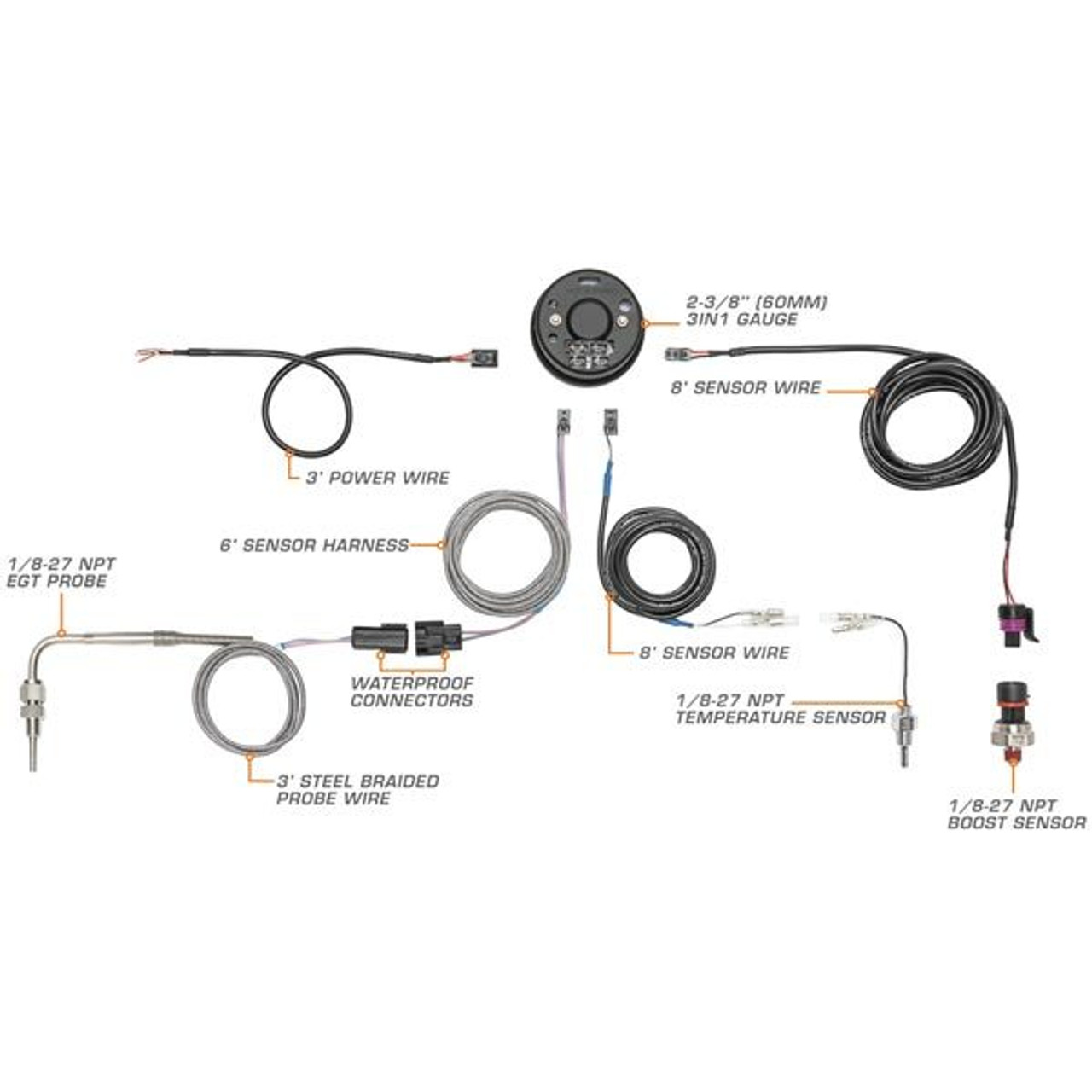
3in1 Black Analog 60 PSI Boost w/ Digital EGT & Temperature Gauge
glowshift boost gauge wiring diagram - What is a Wiring Diagram? A wiring diagram is a simple visual representation in the physical connections and physical layout of an electrical system or circuit. It shows how a electrical wires are interconnected which enable it to also show where fixtures and components could be attached to the system.
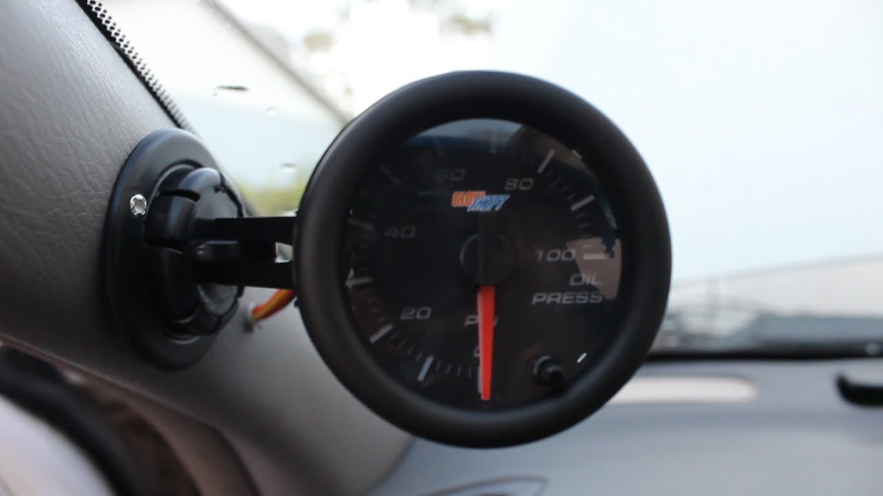
How to install a Glowshift oil pressure gauge
How It Works GlowShift's Oil Pressure Gauges are electronically driven and use a 1/ NPT electronic oil pressure sensor. The sensor can be installed directly to the oil gallery, an oil gallery test port, an oil filter sandwich adapter and an oil cooler adapter as well. Using automotive grade wiring (18 gauge); connect the green wire to the ...
Glowshift Boost Gauge Problem | Veloster Forum
glowshift gauges wiring diagram?? Jump to Latest Follow Hey everyone! Enter your truck HERE to be a part of December's Cummins of the Month Challenge! 1 - 7 of 7 Posts. C. chadc311 · Registered. Joined Oct 8, 2008 · 69 Posts . Discussion Starter · #1 · Aug 17, 2009. Only show this user ...

Elite 10 Color 30 PSI Boost/Vacuum Gauge
GlowShift Gauges, LLC 444 Commerce Lane Suite A West Berlin, NJ 08091 GlowShift.com Gauge Wiring 1. In order to test for power, reconnect the Negative Battery Terminal. 2. It may be necessary to remove the Vehicle Trim and/or Kick Panels in order to gain access to the vehicle's Fuse Box. 3.
Pre wiring my gauges need help asap please | Ford Powerstroke ...
GlowShift Gauges, LLC 444 Commerce Lane Suite A West Berlin, NJ 08091 GlowShift.com Additional Information • The supplied optional gauge visor is intended to be placed on the gauge so that the thickest part is at the top, creating a cover over the gauge to help keep sun glare off of the gauge face.

Black 7 Color 30 PSI Boost/Vacuum Gauge
i got them working. the colors weren't the same as the manual said but i traced them on the diagram and got the right ones. thanks again. EDIT: for anyone that is looking for what i was, do as DeathBySpray said and go with the headlight switch. i was replacing my gauge cluster panel with Glowshift's to hold my 2 gauges so the headlight switch was right there for me. looking at the electrical ...

GlowShift | Wiring Harnesses

GlowShift Digital Series Vacuum Gauge User Manual | 3 pages ...
GlowShift : User Manual

GlowShift 3in1 Analog 60 PSI Boost Gauge Kit with Digital 2200 F Pyrometer Exhaust Gas Temp EGT & 300 F Temperature Readings - 10 Selectable LED ...
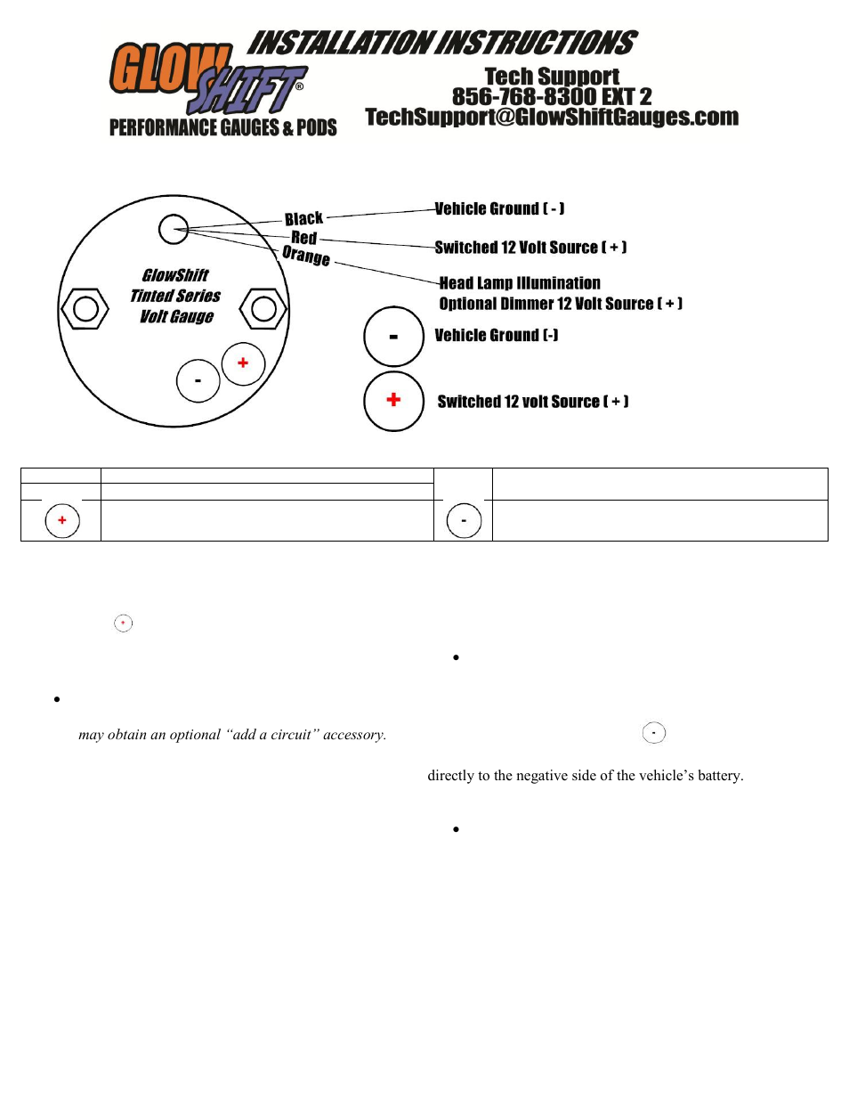
GlowShift Tinted Series Volt Gauge User Manual | 3 pages
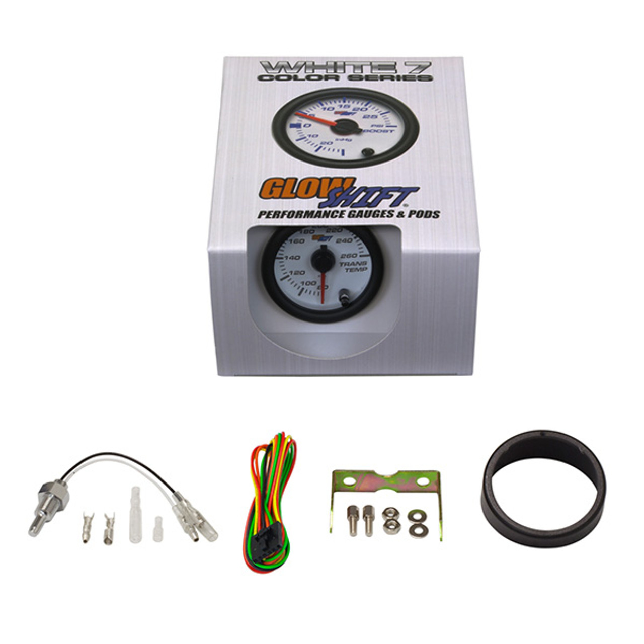
White 7 Color Transmission Temperature Gauge
Black 7 Color 6 Gauge Custom Dashboard Set

GlowShift | Wiring Harnesses

7 Color Series 3 Gauge Wiring Kit with Power Wires Only

Black 7 Color 100 PSI Fuel Pressure Gauge

GlowShift Black 7 Color Custom Cluster Dashboard 6 Gauge Set - 3-3/4" (95mm) Speedometer & Tachometer - 2-1/16" (52mm) Fuel Level, Oil Pressure, Water ...

GlowShift Diesel Gauge Package Compatible with Ford Super Duty F-250 F-350 Power Stroke 1999-2007 - White 7 Color 60 PSI Boost, 1500 F EGT, ...
GlowShift Gauges Installation
GlowShift Black 7 Color 4 Gauge Diesel Set - 60psi Boost ...

MaxTow 3 Gauge Power Wire Harness

Tinted 7 Color Volt Gauge

Tinted 7 Color Dual Needle Air Pressure Gauge
Glowshift wiring | Ford Powerstroke Diesel Forum

GlowShift | Wiring Harnesses
Elite 10 Color 60 PSI Boost Gauge
30 Day Warranty

GlowShift 7 Color Series Oil Pressure Gauges / glowshift-7 ...
GlowShift Diesel Gauge Package Compatible with Dodge Ram Cummins 2500 3500 1998-2002 - Tinted 7 Color 60 PSI Boost, 2400F EGT & 30 PSI Fuel Pressure ...
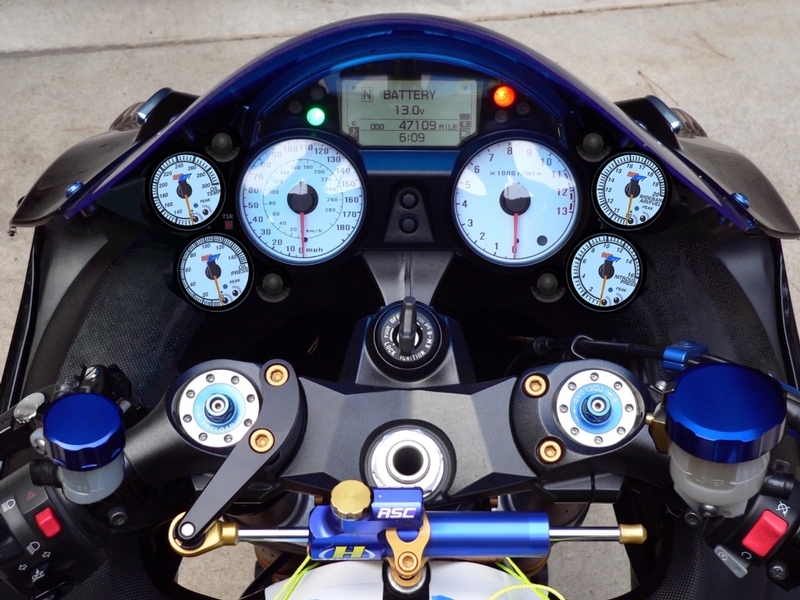
Tachometers - Page 15 - Team-BHP
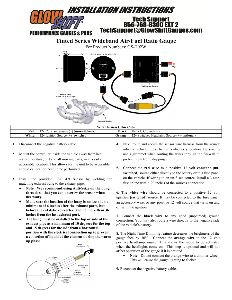
GlowShift Wideband Air / Fuel Ratio Gauge w/ Datalogging ...

GlowShift 10 Color Digital 145 PSI Oil Pressure Gauge Kit - Includes Electronic Sensor - Multi-Color LED Display - Tinted Lens - for Car & Truck - ...
GlowShift Elite 10 Color Narrowband Air Fuel Gauge User ...
0 Response to "37 glowshift gauges wiring diagram"
Post a Comment