39 how to read pressure enthalpy diagram
R12 refrigerant pressure enthalpy chart pdf - Canada ... R12 refrigerant pressure enthalpy chart pdf. In the above equation, P sat is the saturation pressure (in atm.) at a temperature T (in Kelvin), h fg and s fg are enthalpy and entropy of vaporization and R is the gas. r12 pressure enthalpy chart Sat, 22 Dec 2018 07:36:00 GMT r12 pressure enthalpy chart pdf - Conversions and Formulas Pressure Temperature Chart 800.497.6805. Refprop - Nist A reverse Polish type notation was added to read any functional form for the transport properties, eliminating the need to compile a new DLL as new correlations are published. ... A wide variety of property diagrams may be automatically generated, including pressure-enthalpy and temperature-entropy diagrams and (for binary mixtures) temperature ...
How does HyperHeat work? re: comparing heat pumps ... In the 5-ton only. •Increases capacity. •Part of the vapor-injection circuit. •Injects sub-cooled liquid from the condenser into the heat exchanger. •Injects into the mid-port of the compressor. •Sub-cooled liquid then leaves the other side of the heat exchanger further sub-cooled before exiting to the evaporator.

How to read pressure enthalpy diagram
Freon 12 Pressure Enthalpy Diagram Freon 12 Pressure Enthalpy Diagram 1/3 [DOC] Freon 12 Pressure Enthalpy Diagram Automobile air conditioning - Wikipedia In 1954, the Nash Ambassador was the first American automobile to have a front-end, fully integrated heating, ventilating, and air-conditioning system. How Do You Draw An Activation Energy Diagram ... How do I calculate enthalpy? Use the formula ∆H = m x s x ∆T to solve. Once you have m, the mass of your reactants, s, the specific heat of your product, and ∆T, the temperature change from your reaction, you are prepared to find the enthalpy of reaction. Simply plug your values into the formula ∆H = m x s x ∆T and multiply to solve. Enthalpy Composition Diagram - Reflux Ratio - Brewiki Enthalpy-composition diagram for ammonia-water at 1.0 MN/m2 pressure (Example 11.10) Since the actual reflux is 8 per cent above the minimum, then: Point N therefore has an ordinate of (437 + 1547) = 1984 and an abscissa of 0.995. Point M is found by drawing NF to cut the line x = 0.10, through W, at M.
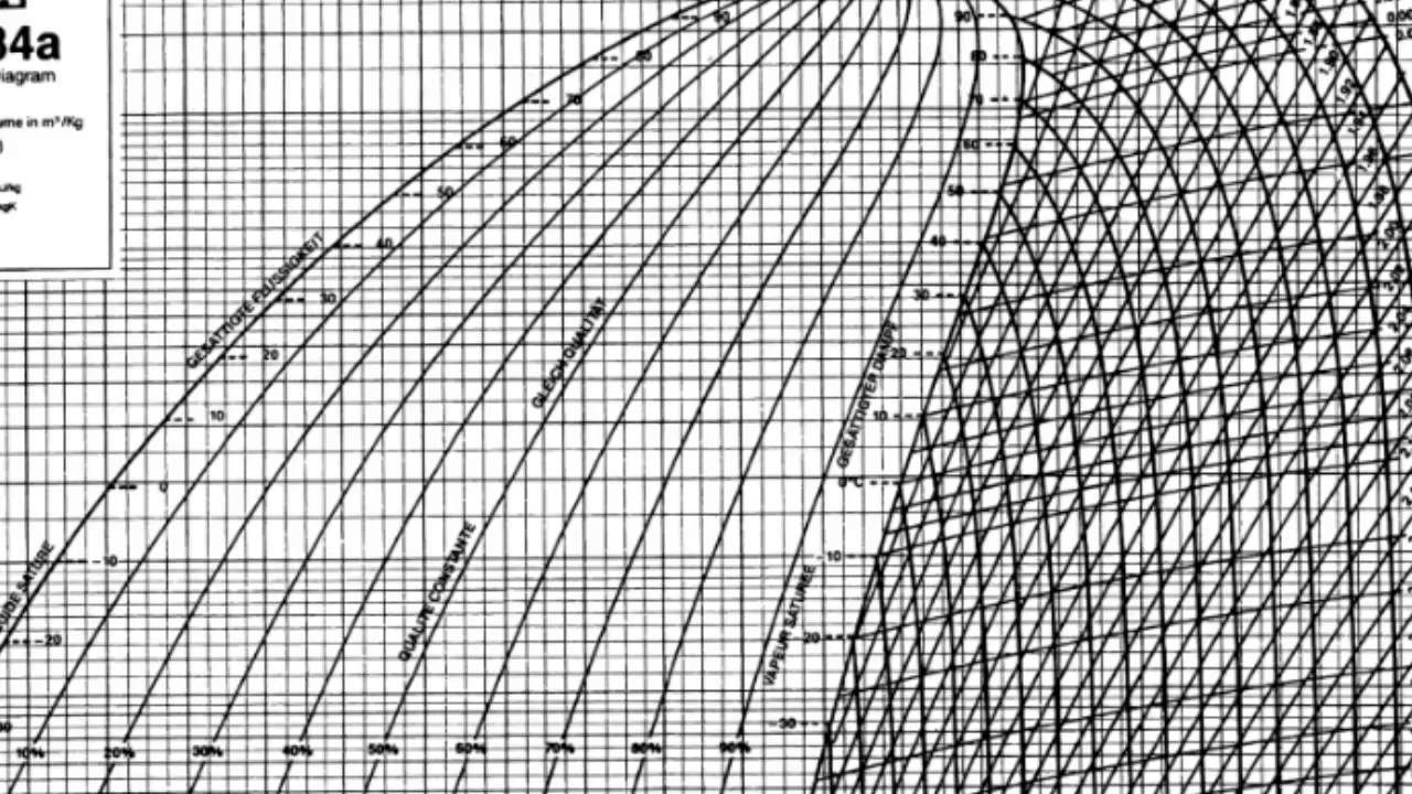
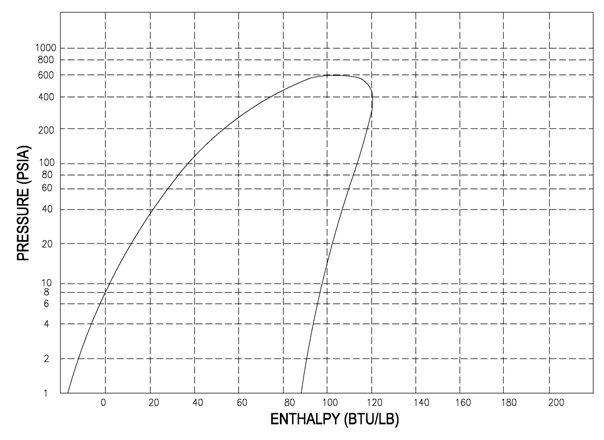
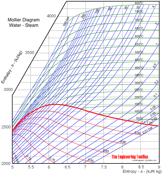
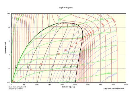
How to read pressure enthalpy diagram. Blank Pressure Enthalpy Diagram enthalpy can be found as ℎ. 2 = 337.32. 𝑘𝑘𝑘𝑘 𝑘𝑘𝑘𝑘. found from the superheated tables because 𝑇𝑇. 2 > 𝑇𝑇. 𝑠𝑠𝑠𝑠𝑑𝑑. for 0.8 MPa. Drawing circuits worksheet Since the inlet temperature and pressure are known along with Refrigerant Ph Diagram - Heat Exchangers - Brewiki Refrigerant Ph Diagram. For a Carnot cycle (where A Q = TA s), the COP for the refrigeration application becomes (note than T is absolute temperature [K]): Thigh_ Tio and for heat pump application: The COP in real refrigeration cycles is always less than for the ideal (Carnot) cycle and there is constant effort to achieve this ideal value. thermodynamics - $\rm CO_2$ Pressure Enthalpy Diagram In ... Im trying to make a 1D model of C O 2 cooling in Python. What I'm currently stuck on is programmatically reading a PH diagram. I have a bottle of C O 2, which is vented to the atmosphere via some cooling tubes. The problem is non-adiabatic and non-isothermal and is compressible. So when I have been doing prior is manually reading the PH diagram ... Mollier diagram with constant temperature lines free ... On Mollier diagram constant pressure line diverge from one another as shown in the figure. From the first and second laws of thermodynamics, the following property relation was obtained, Tds = dh - vdp. (∂ h ∂ s) p = T. This equation forms the basis of the h-s diagram of a pure substance, also called the Mollier diagram.
Ponchon Savarit - Distillation System - Buffalo Brewing Blog Ponchon Savarit. Where Pa and Pb are the vapor pressures of components a and b at a given temperature. The partial pressure p of component a above a binary ideal solution can be calculated by. Where xa is the mole fraction of component a in the liquid. Similarly in a binary mixture, for component b. pb = Pb-xb. Creative Enthalpy Worksheet With Answers - Labelco Thermochemistry Worksheet 1 1. Enthalpy online worksheet for High school. Enthalpy stoichiometry worksheet answers. No Question Answer 1 State which of the following reactions are exothermic and which are endothermic. The heat content of a chemical system is called the enthalpysymbol. Step 3. How to Draw & Label Enthalpy Diagrams - Video & Lesson ... Let's look at the elements of this enthalpy diagram. First, as noted, the y -axis is labeled 'enthalpy' and the x -axis is labeled 'reaction progress.' Then we have the actual energy diagram plot.... Steam Table And Mollier Diagram Pdf, Mollier Chart Pdf ... On the diagram, lines of constant pressure, constant temperature and volume are plotted, so in a two-phase region, the lines of constant pressure and temperature coincide. The work done in a process on vapor cycles is represented by length of h , so it can be measured directly, whereas in a T—s diagram it has to be computed using thermodynamic relationship between thermodynamic properties. r.k.rajput - steam table & mollier chart. Units By R. S Khurmi, J.
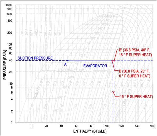
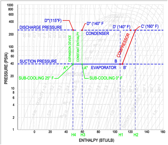
The lower horizontal line of the refrigeration cycle ... The lower horizontal line of the refrigeration cycle plotted on pressure-enthalpy diagram represents A). Condensation of the refrigerant vapour B). Evaporation of the refrigerant liquid C). Compression of the refrigerant vapour D). Metering of the refrigerant liquid The lower horizontal line of the refrigeration cycle plotted on pressure-enthalpy diagram represents 2 Compressor 2 Evaporator P-h Diagram - Air Conditioning Next determine the enthalpies at the state points. hx = hg at -30°C = 1423 kJ/kg h2 = h at 517 kPa after isentropic compression = 1630 h^ = h at 1557 kPa after isentropic compression = 1625 hs = hf at 40°C = 390.6 h6=h5 = 390.6 h-j = hf at 5°C = 223 h8 =h7 = 223 The mass rates of flow are 180 kW W7=W8~W2 = W1= kg/s PDF Psychrometric Chart Tutorial A Tool For Understanding Calculating Relative Humidity and Dewpoint The Pressure-Enthalpy Diagram | Part 1: Theory ... physical and thermodynamic properties such as dry bulb temperature, wet bulb temperature, humidity, enthalpy, and air density. Download Also: McQuay ... How to Read a Psychrometric Chart: 11 Steps (with Pictures) Understand Dew Point and Absolute Moisture ... - HVAC School We would simply draw a line up from the bottom at 75°F (23.88°C) until we hit the curved 50% line. Then, go right (or left) until you bump into the grains of moisture and then the dew point scale. Now you know at what temperature that same air mass will start to condense water.

Chapter 4 | Thermodynamics
P-V and T-S Diagrams - NASA As described on the work slide, the area under a process curve on a p-V diagram is equal to the work performed by a gas during the process. On the right of the figure we have plotted the temperature versus the entropy of the gas. This plot is called a T-s diagram. Lines of constant pressure curve from the lower left to upper right on a T-s diagram.

Saturated, Multi-Phase Systems and Proof that a Watched Pot ...
Air Conditioner Pressure Chart Pressure Enthalpy Diagram For Refrigerant R22 And R422d. We have the low and the high. Pressure for all temperatures of this refrigerant. Anyway here is the best DIY help for AC I know. With an ambient temperature of 70 F 21 C an orifice tube system with a cycling switch should have approximately 150-250 psi 10342-17237 kPa high-side pressure ...

Understanding refrigerant glide - Plumbing & HVAC
R-134a TEMPERATURE PRESSURE CHART - Discover alternatives R134a refrigerant has zero ozone-depleting potential (ODP)) and is ubiquitous with the best refrigerant R12. R134a is the ideal refrigerant for working at high boiling and condensation conditions. R134a is a non-competitive refrigerant that has zero temperature "slip.". Always use polyester oil when working with R134a.
Refrigeration - Pressure Enthalpy Chart -refrigerant states
Pressure Enthalpy Diagram Methane Floxii Doc Download Download Ebook Pressure Enthalpy Diagram Methane Floxii Pressure Enthalpy Diagram Methane Floxii Sci-tech Book Profiles Includes title page, table of contents, list of contributors, preface and all indexes of each ... essential reading for graduate students and researchers. The efficient and profitable production of fish, crustaceans, and other ...

Category: Using Pressure Enthalpy Diagrams - FUNDAMENTAL ...
Reading Wiring Diagrams In HVAC Loads usually sit at the end of a circuit, after power moves from the power supply through an inline switch or switches, the load or loads are powered up and begin to function. Loads are things like motors, compressors, contactor or relay coils and light bulbs. Loads perform work and draw amperage. This basic wiring diagram includes all three ...
Pressure-Enthalpy Diagram
Mollier Diagram - Heat Recovery - Beyond Discovery This shows about 1,269 Btu/lbm (1,268.8). Fig. 6-5 Mollier Diagram for Steam (English Units). Source: Babcock & Wilcox. First determine the enthalpy difference per lbm at each condition: 1269 Btu/lbm - 1200 Btu/lbm = 69 Btu/lbm. Then multiply the difference in enthalpy per lbm by the total lbm of steam being superheated (by about 118°F) to ...
Carbon Dioxide: Pressure - Enthalpy Diagram Enthalpy, kJ/kg ...
Dupont R134a Ph Diagram Filetype Pdf Pressure Enthalpy Diagram. On the P-H diagram, pressure is indicated on the y-axis and enthalpy is indicated on the x-axis. Refrigerant R22 - Properties Documents. A common skill, that is required of a professional engineer, is to determine the work done by the compressor. Figure 8 illustrates the horizontal temperature lines in the mix region.

Pressure / Enthalpy Diagram Example - HVAC School
Blank Pressure Enthalpy Diagram - albedaiah.com phase diagrams and related properties. This chapter gives a consistent and axiomatic approach to fluid thermodynamics; it avoids using activity coefficients. Further chapters are dedicated to solid-fluid phase equilibria and global phase diagrams (systematic search for phase diagram classes). The appendix contains numerical algorithms needed ...
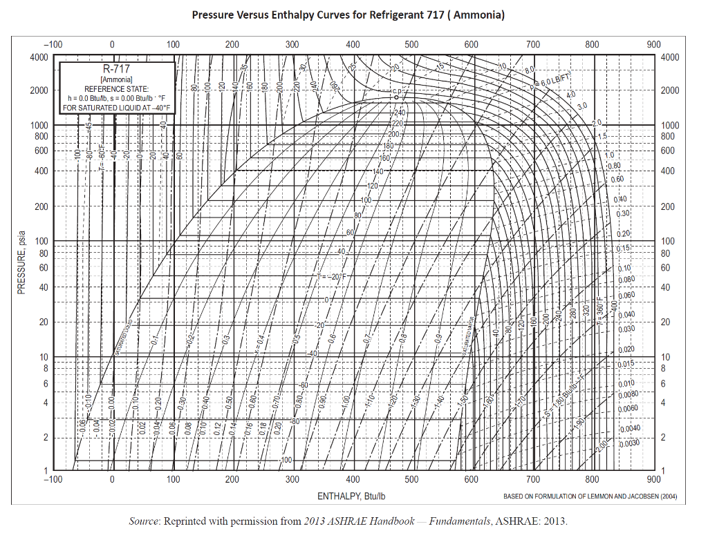
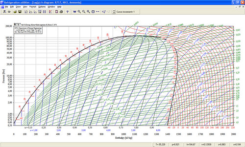
Solved 501. An ammonia (R-717) refrigerant brine chiller ...
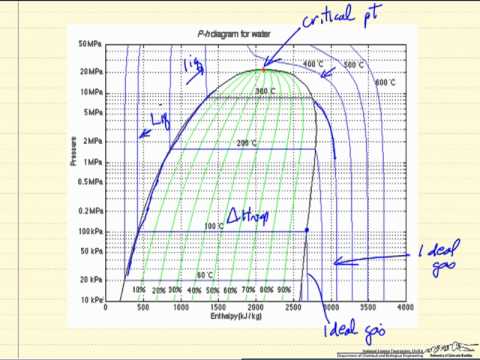
The Vapor Pressure and Enthalpy of Vaporization ... A two dimensional phase diagram shows pressure as a function of temperature. The lines on the diagram represent the temperature and pressure combinations at which two phases can coexist in equilibrium. A point where three phases can coexist is called a triple point. A portion of the phase diagram for water is shown in Figure 2. Latent Heat
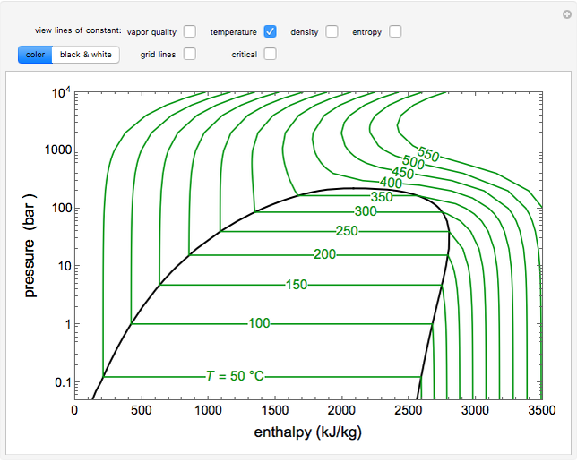
Thermodynamics 1 Simulations - LearnChemE
HFC-134a Refrigerant & 2nd Law of Thermodynamics | Physics ... Jan 6, 2022. #1. Devin-M. 507. 435. I am trying to reconcile HFC-134a refrigerant with the 2nd Law of Thermodynamics. I shouldn't be able to extract useful work from a single temperature reservoir. Suppose I use a refrigeration / heat pump cycle with HFC-134a as shown below. -Compressor adds 29 kJ/kg increasing refrigerant temperature from -60C ...
P-H Diagram Thermodynamics | HVAC and Refrigeration PE Exam ...
Enthalpy Change: Standard Enthalpy, Properties, Types Read Also : Thermodynamics Enthalpy and Change in enthalpy (H and dH) Enthalpy is the sum of the internal energy(U) held within the molecules of a matter with its volume(V), and the pressure(P). It is the heat content of the system at a constant pressure. But it is impossible to know the amount of internal energy as it can be enormous at any measurable volume and pressure.
How a Water Source Heat Pump Works: Thermodynamics 101 ...
Diagramme De Mollier R22 Pdf Read online and download pdf ebook r22 mollier diagram. R22 pressure enthalpy chart pdf. Teamcenter vis mockup pdf. Pressure is shown on the verticle axis. r12 pressure enthalpy diagram for. The difference being that in refrigeration the chart plots pressure against enthalpy and in air.

Mollier Diagram - an overview | ScienceDirect Topics
Enthalpy Composition Diagram - Reflux Ratio - Brewiki Enthalpy-composition diagram for ammonia-water at 1.0 MN/m2 pressure (Example 11.10) Since the actual reflux is 8 per cent above the minimum, then: Point N therefore has an ordinate of (437 + 1547) = 1984 and an abscissa of 0.995. Point M is found by drawing NF to cut the line x = 0.10, through W, at M.

Mollier Diagram - an overview | ScienceDirect Topics
How Do You Draw An Activation Energy Diagram ... How do I calculate enthalpy? Use the formula ∆H = m x s x ∆T to solve. Once you have m, the mass of your reactants, s, the specific heat of your product, and ∆T, the temperature change from your reaction, you are prepared to find the enthalpy of reaction. Simply plug your values into the formula ∆H = m x s x ∆T and multiply to solve.
Enthalpy Entropy (h-s) or Mollier Diagram | Engineers Edge
Freon 12 Pressure Enthalpy Diagram Freon 12 Pressure Enthalpy Diagram 1/3 [DOC] Freon 12 Pressure Enthalpy Diagram Automobile air conditioning - Wikipedia In 1954, the Nash Ambassador was the first American automobile to have a front-end, fully integrated heating, ventilating, and air-conditioning system.

Pressure-Enthalpy As A Service Tool | ACHR News

Pressure-enthalpy diagram for the tested refrigerants ...
Tutorial: Pressure-Enthalpy Diagrams | AIChE

Thermodynamic Properties of CO2 (updated 12/15/2008)
PRESSURE-ENTHALPY CHARTS AND THEIR USE INTRODUCTION The ...
P-H Diagram Thermodynamics | HVAC and Refrigeration PE Exam ...
Refrigeration Basics - Definitions Part 2
P-H Diagram Thermodynamics | HVAC and Refrigeration PE Exam ...
PRESSURE-ENTHALPY CHARTS AND THEIR USE INTRODUCTION The ...
PRESSURE-ENTHALPY CHARTS AND THEIR USE INTRODUCTION The ...
Engineering Thermodynamics A Graphical Approach
Engineering Thermodynamics A Graphical Approach

Wolfram Demonstrations Project
PRESSURE-ENTHALPY CHARTS AND THEIR USE INTRODUCTION The ...

File:R22 ph.gif - Wikipedia
Water-Steam Mollier Diagram

Pressure-Enthalpy diagram for vapour compression cycle ...
Analysis of the Mollier diagram to simplify the calculations ...
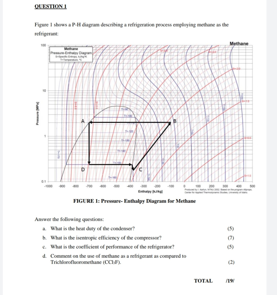
Solved QUESTION 1 Figure 1 shows a P-H diagram describing a ...
Moist Air - the Mollier Diagram

Heat Pump COP

PDF) Pressure-Enthalpy Diagram for Water and Steam Based on ...
Pressure Enthalpy Chart ?

Category: Using Pressure Enthalpy Diagrams - FUNDAMENTAL ...
0 Response to "39 how to read pressure enthalpy diagram"
Post a Comment